


TABLE OF FIGURES
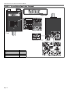
Figure 1: Top and Bottom Panel Label Placement....................2
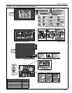
Figure 2: Side and Back Panel Label Placement......................3
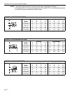
Figure 3: Standard Reflector.....................................................5
Figure 4: One Side Reflector.....................................................6
Figure 5: Two Side Reflectors ...................................................6
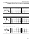
Figure 6: 45° Tilt Reflector ........................................................6
Figure 7: U-Tube, Standard Reflector........................................7
Figure 8: U-Tube, 45°................................................................7
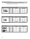
Figure 9: U-Tube, Opposite 45° Reflector .................................7
Figure 10: 2-Foot Deco Grille and Protective Grille ...................8
Figure 11: Lower Clearance Shield ...........................................8
Figure 12: Venting.....................................................................8
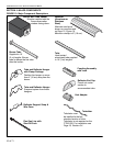
Figure 13: Major Component Descriptions.............................. 10
Figure 14: Critical Hanger Placement .....................................13
Figure 15: Linear Heater Assembly Overview ........................14
Figure 16: Linear Heater Layout Overview.............................. 15
Figure 17: U-Tube Heater Assembly Overview ......................23
Figure 18: U-Tube Heater Layout O
verview ...........................24
Figure 19: Reflector Joint Detail ..............................................26
Figure 20: Tube Termination...................................................32
Figure 21: Gas Connection with Flexible Gas Hose ...............38
Figure 22: Zone Sensor Wiring Diagram.................................39
Figure 23: Central Heater Jumper Settings.............................40
Figure 24: Satellite Heater Jumper Setting..............................41
Figure 25: Communication Wiring within a Zone of Heaters ...42
Figure 25: Communication Wiring within a Zone of Heaters
(continued).............................................................43
Figure 26: Thermostat Control Wiring Diagram.......................44
Figure 27: Analog Control Signal Wiring Diagram...................47
Figure 28: Potentiometer Control Wiring Diagram...................48
Figure 29: Modulating Thermostat Wiring Diagram
(LonWorks
®
[4-20 mA] optional).............................49
Figure 30: Modulating Thermostat Wiring Diagram
(LonWorks
®
[2-10Vdc with 500 Ohm resistor]
optional).................................................................50
Figure 31: Modulating Thermostat Wiring Diagram
with BACnet
®
(optional) .........................................51
LIST OF TABLES
Table 1: Contents of Burner Carton........................................11
Table 2: Contents of Core and Extension Packages ..............11
Table 3: CTH3-Series Component Package Guide................11
Table 4: Cable Requirements .................................................46