


9
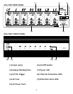
DESCRIPTION OF UNIT: REAR PANEL
(1) Inputs
The audio inputs for the GFA-7605 and GFA-7607 are
through high-quality, gold-plated RCA jacks to minimize
high-frequency losses, noise, etc. They will accept
standard RCA-type plugs, one for each of the channels. To
insure that the performance designed into the amplier is
preserved, you should use the highest quality audio cables
possible. There are many cables which are color-coded
and specically designed for this application. Your ADCOM
dealer can help select the best cable for your needs.
(See CONNECTING THE GFA-7605/7607 for more information).
(2) Outputs
The GFA-7605’s and GFA-7607’s connections to the
loudspeakers are made through high-grade, 5-way,
gold-plated binding post terminals. There are two
terminals for each speaker, which are colored RED for the
positive (+) output and BLACK for the negative (-) output.
The binding posts will accept a variety of connector types;
the most secure and prevalent of these is the “U”-type
spade connectors (at least 0.25’’ wide and maximum width
of 0.57”). The terminal will also accept bare wire (up to
AWG1O) and “banana” type plugs (single or dual).
(See CONNECTING THE GFA-7605/7607 for more information).
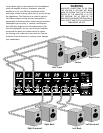
(3) I2V DC Trigger
The GFA-7605 and GFA-7607 are very high power ampliers
and as such must be directly connected to the wall outlet
or an appropriate surge protector or AC line conditioner.
It must never be connected to the ‘switched’ outlets on
the rear panel of a pre-amplier. Usually this would mean
that when you turn on/off your pre-amplier you would
have to turn on/off your power amplier separately. We
have however provided the ability to control the OFF/ON
function of the GFA-7605/7607 by a l2V DC output jack
on the rear of certain ADCOM pre-ampliers and tuner
preampliers. When using this feature the front panel
Power Switch must be left in the in “on” position. To
connect you will need a monaural mini phone plug to
monaural mini phone plug cable of appropriate length (not
included) to reach from the rear panel of the amplier to
the rear panel of the pre-amplier. Contact your dealer for
information on using this feature with ADCOM and other
brand pre-ampliers.
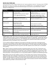
(4) AC Fuse
The AC Fuse protects the electronic circuits of the GFA-
7605/7607. This fuse, normally, will fail only if there is an
overload within the GFA-7605/7607. It may, however, fail if
the amplier attempts to deliver very high power into very
low-impedance loudspeakers. In either case, BE SURE TO
REPLACE THE AC Fuse ONLY WITH AN EXACT REPLACEMENT
FUSE. The proper fuse values are:
GFA-7605 for 120 volt operation — Fuse Rating: 13 Amp
GFA-7605 for 230 volt operation — Fuse Rating: 6.5 Amp
GFA-7607 for 120 volt operation — Fuse Rating: 15 Amp
GFA-7607 for 230 volt operation — Fuse Rating: 8 Amp
Before attempting to replace a failed fuse, be certain
to unplug the AC Power Cord from the AC wall outlet to
prevent possible electrical shock. Replace the AC Fuse
only with one identical in type and rating as printed on
the rear panel. DO NOT USE ANY SUBSTITUTE FUSES WITH
DIFFERENT RATINGS OR VALUES. Failure to observe this
precaution may cause serious damage to the amplier
circuits, may create a hazard re, and may void the warranty.
If the Power LED (7) does not glow, it may be an indication
that the AC fuse has blown. If you are using the 12V
DC Triggering feature it may be possible that there is
a problem with that connection. To determine if the
problem is caused by a malfunction in the 12V DC system,
remove the small plug inserted into the I2V DC Triggering
jack. Press the front panel power switch to turn off the
amp, and immediately re-press the power switch. If the
problem is caused by the 12V DC triggering circuit the amp
will turn on and the LED will glow. DO NOT attempt repair
of the 12V DC system. If you are not sure, or the amplier
displays other symptoms, please consult the RESOLVING
PROBLEMS section on page 12.
Fuse replacement
To remove the fuse-holder cap, you will need a 1/4”
standard at-blade screwdriver. Place the screwdriver
in the recessed slot in the cap. Turn the cap 1/8-turn
counter-clockwise, until the cap pops out towards you.
Grasp the cap with your ngers and pull it completely out.
The fuse is inserted in the back of the cap; gently pull it free.