


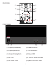

To set the amplifi er in bridged mono operation, fl ip the STEREO/BRIDGED input switch into the BRIDGED position. When
in the bridged mono mode, input to the amplifi er is made only through the LEFT input jack. The connection to the RIGHT
input jack should be removed since the right-channel input portion of the amplifi er is inoperative.
Only a single loudspeaker is to be connected to the GFA-555se when in the bridged mono mode. Please note that
connections made to the loudspeaker from the GFA-555se, when used in the bridged mono mode, are different from
those made when the amplifi er is used in the stereo mode. The LEFT RED output binding-post terminal (labeled
BRIDGED MONO OUTPUT “+”) should be connected to the loudspeaker input terminal color-coded RED (or labeled
POSITIVE, “+”, POS, 8 OHMS or 4 OHMS). The RIGHT RED output binding post terminal on the amplifi er (labeled BRIDGED
MONO OUTPUT “-”) should be connected to the BLACK loudspeaker terminal (or labeled NEG, “-”, C, COM, COMMON,
G, or GROUND). Please note that if you want to insure correct stereo phasing with optimal bass response, you must
observe these connections precisely.
Although the GFA-555se can generate a substantially greater amount of power in the bridged mono mode than when it
is in its normal stereo mode, it requires the use of loudspeakers whose nominal impedance does not drop below 4 ohms.
It is not recommended that the GFA-555se be used in the bridged mono mode into loudspeakers, or multiple loudspeaker
loads, which drop in value substantially below 4 ohms. Otherwise, you may trigger the THERMAL PROTECTION or blow
one of the DC RAIL FUSES. A little known fact is that when any amplifi er is operated in the bridged mode, the load is
“split” between the two amplifi ers in the bridged confi guration. Therefore, an 8-ohm loudspeaker will be seen by the
amplifi er as if it were a 4-ohm load; a 4-ohm loudspeaker load will be seen by the amplifi er as a 2-ohm load.
NOTES:
a) If the connections described above are followed exactly, the GFA-555se will be polarity correct, that is, it will not
invert “phase”. Any positive-going signal at its input will appear as a positive-going signal at the loudspeaker.
b) For use in professional installations, the GFA-555se may be mounted in a standard 19-inch rack using the optional
RM-7 rack-mount adaptors available through ADCOM dealers. If the GFA-555se is to be mounted on a rack, along with
other components which are interconnected to the GFA-555se, the amplifi er’s chassis must be insulated from the
metal-rack rails to prevent ground loops, especially if the rack is grounded to “earth”, and to avoid defeating the audio
grounding scheme of the power amplifi er (the audio-input grounds are isolated from and above the chassis ground).
Please consult the instruction sheet packed with the optional rack-mount adaptors for more information.
c) The DC RAIL FUSES provide protection for the output stages and power supply in the event of excessive current
demands from the amplifi er, either long-term or short-term. If the amplifi er ceases to operate, either on one or both
channels, particularly during high-level passages, or long-term high-volume playback, and the POWER LED glows while
the THERMAL PROTECTION LED is out, the chances are that one or both of the DC RAIL FUSES on that channel, or both
channels, are blown. In the event that the DC RAIL FUSES need to be replaced, refer servicing to qualifi ed service
personel. DO NOT USE ANY SUBSTITUTE FUSES WITH DIFFERENT RATINGS, TIME-CURRENT CURVES OR VALUES. Failure to
observe this precaution may cause serious damage to the amplifi er circuits, MAY CREATE A FIRE HAZARD, AND MAY VOID
YOUR WARRANTY.
8