


SUBWOOFER ADJUSTMENT & USE
SUBWOOFER INITIAL CONTROL SETTINGS
• Set the LOW PASS FREQUENCY Control to its center position.
• Set the LEVEL Control fully counterclockwise to MIN. You’ll reset this control
after you make other adjustments.
ADJUSTING THE SUBWOOFER CONTROLS
• Play a program on your system. For the following adjustments, use the Dolby
ProLogic Normal surround mode and select a movie that has a Dolby Surround
soundtrack with a lot of music, or play a music CD. Adjust the receiver’s volume
control for a comfortable sound level from the system speakers.
• Increase the Subwoofer’s LEVEL Control setting clockwise, so that you hear the
deep bass. Adjust the control for a natural, musical balance that has plenty of
deep bass sound when it is actually present in the music.
• Listen carefully to bass voices and, if needed, adjust the LOW PASS
FREQUENCY Control so that they sound natural. Setting the frequency too
high will make deep voices sound excessively “chesty” or resonant and will
give the upper bass in music a “one-note” quality. Setting the frequency too
low will make deep voices sound “thin” and will give music a lack of
“warmth”.
• Make fine adjustments until the program has satisfying and natural sound
quality on both bass voices and music.
MOUNTING BRACKETS
The speaker’s bracket leg can be used to support the speaker in shelving in either a
vertical or horizontal position, and to adjust the speaker’s direction. Connect the
speaker wire before you put the bracket leg in its final position.
A knurled clamp screw holds the bracket leg to the speaker. Loosen the screw, posi-
tion the leg for vertical or horizontal placement of the speaker, adjust the leg’s posi-
tion to aim the speaker, and re-tighten the clamp screw finger-tight. Do not
use a tool to tighten the screw. Note: For the satellite speakers,a single 1/4"-20
insert has been added for use with aftermarket single post mounting brackets.
TROUBLESHOOTING
SUBWOOFER POWER INDICATOR LED DOES NOT LIGHT
• Check that the Subwoofer’s POWER Switch is in the AUTO ON position.
• If the POWER Switch is in the AUTO ON position, check the AC outlet the
Subwoofer is plugged into to be sure that it is live. You can use a tester or
plug-in a lamp to check it.
• If the AC outlet is live, either the power cord or Subwoofer has a problem.
Unplug the power cord from the AC outlet and check the fuse by unscrewing the
center piece from the holder. If it is blown, replace the fuse only with a fuse of
the same type and rating. If this doesn’t help, take the Subwoofer to your
dealer for service – THERE ARE NO USER SERVICEABLE PARTS INSIDE.
NO SOUND FROM THE FRONT SPEAKERS.
• Be sure the Receiver and Subwoofer POWER Switches are in the On positions.
• Check the Receiver’s Volume Control Setting - if it is all the way down, there
won’t be any sound.
• Check that the Receiver’s Input Selector is set to an active source of audio
signals and that a Tape Monitor Loop is not engaged.
• Be sure that the Receiver’s Speaker Selector switch is turned on to the
terminals [A or B, 1or 2] that you have your Front speakers connected to. If the
Receiver has a headphone jack, you can use headphones to check the Receiver
for output.
• Check the wires and connections from the Receiver’s Front Speaker Output
terminals to the Subwoofer’s SPEAKER-IN terminals.
• Try removing the Subwoofer from the system, leaving your Front speakers
connected to the Receiver. If there still is no sound, take the Receiver to your
dealer for service.
NO SOUND FROM THE SUBWOOFER
• First, be sure there is sound from the Front speakers and that the Receiver is
working correctly as outlined above.
• Check the Subwoofer’s LEVEL Control. If it is all the way counter clockwise,
there may be no sound.
• The Subwoofer only reproduces deep bass sound. If the program has no deep
bass, the Subwoofer will not make any sound. Play a program with plenty of
bass, such as jazz or rock music, or an action movie.
• If everything else checks OK, take the Subwoofer to your dealer for
service - THERE ARE NO USER SERVICEABLE PARTS INSIDE.
SPECIFICATIONS
Center Channel
Driver Compliment: Dual 4" woofers with
1
/2" PEI tweeter
Frequency Response: 80Hz-20KHz ±3dB
Sensitivity: 91dB
Nominal Impedance: 8 ohms
Recommended Amplifier Power: 10 to 100 Watts
Finish: Black ABS cabinet
Dimensions (HxWxD): 4
3
/8" x 15
1
/8"x 4
7
/8"
Satellites
Compliment: 4" woofer with
1
/2” PEI tweeter
Frequency Response: 80Hz-20kHz ±3dB
Sensitivity: 89dB
Nominal Impedance: 8 ohms
Recommended Amplifier Power: 10 to 100 Watts
Finish: Black ABS cabinet
Dimensions (HxWxD): 7” x 4
3
/
8" x 5
1
/
8"
Subwoofer
8” long throw woofer in front-firing design
Frequency Response: 35Hz to 150Hz
Amplification Power Output: 100 Watts RMS into 4 Ohms
Total Harmonic Distortion: 10% @ 100 Watts output
Signal-to-Noise Ratio: >90 dB
Variable crossover: 50-150Hz
Special Features:
2 pair 5-way gold binding posts for high level input
1 pair RCA input for low level input and one pair for output
Finish: Black ash
Dimensions (HxWxD): 13
3
/4" X 11
3
/4" X 13"
IMPORTANT SAFETY PRECAUTIONS
ATTENTION:
Please read these instructions thoroughly before attempting to operate your AR
Surround System. Be sure to save this manual for future reference. Also save your bill
of sale, as it may be required for warranty service.
CLEANING - Do not use liquid cleaners or aerosol cleaners. Use a damp cloth for
cleaning.
ATTACHMENTS - Do not use attachments not recommended by AR as they may
cause hazards.
WATER and MOISTURE - Do not use the AR Surround System near water - for
example: near a bath tub, wash bowl, kitchen sink, or laundry tub; in a wet basement,
near a swimming pool, or similar locations.
ACCESSORIES - Do not place the AR Surround System on an unstable cart, stand,
tripod, bracket or table. The product may fall, causing serious injury to a child or
adult,and serious damage to the product. Use only with cart, stand, tripod, bracket or
table recommended by AR or sold with the AR Surround System. Any
mounting of the speakers should follow AR’s instructions and should use a
mounting accessory recommended by AR.
OBJECT AND LIQUID ENTRY - Never push objects of any kind into this product
through openings as they may touch dangerous voltage points or short-out parts that
could result in a fire or electric shock. Never spill liquid of any kind on the AR Surround
System.
SERVICING - Do not attempt to service the AR Surround System yourself. Opening or
removing covers may expose you to dangerous voltage or other hazards. Refer all
servicing to qualified AR service personnel.
DAMAGE REQUIRING SERVICE - Refer servicing to qualified service personnel under
the following conditions:
A. If liquid has been spilled, or objects have fallen into the product.
B. If the product has been exposed to rain or water.
C. When the product exhibits a distinct change in a performance
REPLACEMENT PARTS - When replacement parts are required, be sure the service
technician has used replacement parts specified by AR or those having the same
characteristics as the original part. Unauthorized substitutions may result in fire,
electric shock, or other hazards. NOTE: See section on “How to Obtain Service”.
SAFETY CHECK - Upon completion of any service or repairs to this product, ask the
service technician to perform safety checks to determine that the product is in proper
operating condition.
WALL OR CEILING MOUNTING - The AR Surround Sound System has 1/4 x 20
inserts for mounting to walls and should be mounted to a wall or ceiling as
recommended by AR.
HEAT - The AR Surround System should be situated away from heat sources such as
radiators, heat registers, stoves, or other products (including amplifiers) that
produce heat.
HC4B SURROUND SYSTEM
Contents of Carton:
4 each 2-way Matching Satellites , Shielded
1 each 2-way Center Channel, Shielded
1 each Subwoofer
CENTER AND SATELLITE SPEAKERS Your five surround speakers consist of 4
matching Satellites and a Center Channel Speaker. The Satellites are the smaller set
while the Center Channel has a horizontal orientation.
SUBWOOFER Your Subwoofer delivers powerful, deep bass sound output for a
natural, life-like sonic experience. Please follow the directions in this manual to
achieve the best performance from your system.
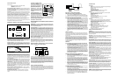
HOW TO PLACE YOUR SYSTEM COMPONENTS Locate the Center Channel on top
of or under the television or monitor. One of the Satellite Speakers should be located
on either side of the television.
Your Subwoofer must sit on the floor, in a corner to work properly. The floor and
corner are actually a part of the Subwoofer’s design.
Place your Subwoofer in the corner nearest your system’s electronic
components to keep wire or cable runs short.
CONNECTING THE SURROUND SPEAKERS Your Receiver will have clearly marked
terminals for connecting the Satellite and Center Channel Speakers. The most common
type of connection is spring loaded. Press down on the tab and insert the stripped wire
tips into the opening.
IMPORTANT: Always connect the red (+) terminal on the Receiver to the red (+)
terminal on the corresponding Speaker i.e. Front Left. Connect the corresponding black
(-) terminal on the Receiver to the black (-) terminal on the same Speaker. Continue until
all of the speakers have been connected in this manner.
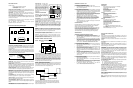
SUBWOOFER CONTROLS & CONNECTIONS
POWER CORD Plug the power cord into an AC wall outlet or other AC outlet
capable of supplying at least 400 Watts.
POWER SWITCH Turns the AC supply completely OFF or sets the Subwoofer to AUTO
ON operation. In AUTO ON, the Subwoofer is in standby mode until it detects an audio
signal input, then the Subwoofer turns on automatically. A few minutes after audio
input signals cease, the Subwoofer automatically returns to standby mode.
POWER INDICATOR LED This LED is unlit when the AC power switch is OFF. It glows
red when the Subwoofer is in standby mode ad green when the Subwoofer is on.
FUSE 250V 2A This fuse protects against internal and external faults. If the POWER
switch is ON and the power indicator LED is unlit, unplug the power cord from the AC
and the back of the amplifier, then pry up the rectangular fuse holder and check the
fuse. IMPORTANT If the fuse is blown, replace it only with a fuse of the same type and
current rating.
L ,R SPEAKER OUT & IN - See Connection Option 1 These terminals are for making
connections using speaker wire. If you use this option, do not use Option 2.
LINE IN & LINE OUT - See Connection Option 2 These are for connections using audio
cables. If you use this option, do not use Option 1.
LOW PASS FREQUENCY CONTROL Adjusts the upper frequency limit for audio sig-
nals going to the Subwoofer amplifier. This control helps you adjust the system’s tonal
balance.
LEVEL CONTROL Balances the loudness of the Subwoofer relative to the Front speak-
ers and compensates for room effects on the Subwoofer’s output.
PHASE SWITCH The Phase Switch
controls the phase of the Subwoofer’s
output relative to the front speakers.
Listen carefully to the sound quality while
playing a CD with low bass. Select the
position of the switch that produces the
fullest deep bass without boominess. You
may need to readjust the Level and Low
Pass Frequency controls after setting the
Phase Switch.
CONNECTING YOU SUBWOOFER
IMPORTANT: When you make connec-
tions. make sure that the power switches
of all components, including the
Subwoofer, are OFF.
AUDIO CABLES If you are connecting the Subwoofer into a system made up of sep-
arate components (preamp & power amps), you will need audio cables long enough to
reach the Subwoofer from the preamplifier and the power amplifier.
SPEAKER WIRE Typical speaker wire has a pair of separate conductors with
insulating jackets that are molded together. We recommend that you use 16-gauge
speaker wire for hooking your Receiver to your Front speakers. To make
connections to the Subwoofer in parallel with the Front speakers easier, the
speaker wire connecting the Receiver to the Subwoofer can be smaller (higher gauge
number), since the Subwoofer does not draw large amounts of power through these
wires.
POLARITY All speakers in a system must be connected with the same polarity.
Speaker wire is marked for polarity so that you can identify which wire in the pair is
which. Polarity is shown by a color strip on the insulation, by ridges molded into the
insulation, or by the colors of the wires - one copper and one silver.
Strip the insulation from speaker wire ends to reveal the bare conductors before
connecting to Receiver, Subwoofer or Speaker terminals.
IMPORTANT Always connect the red + terminal on the Receiver to the red +
terminal on the Subwoofer, and the black - terminal on the Receiver to the black -
terminal on the Subwoofer. The same is true for hooking the Receiver outputs to the
Front speakers: red + to red +, and black- to black-.
IMPORTANT USE OPTION 1 OR OPTION 2, NOT BOTH
.
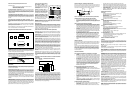
OPTION 1 – CONNECTION WITH SPEAKER WIRE
Connect speaker wires from the Receiver’s front left and right speaker outputs to the
Subwoofer’s Speaker Level-In connections. Connect left channel to left input and right
channel to right input. You have the option of connecting your main speakers to the
speaker B outputs on your Receiver, if it is so equipped or you also have the option of
connecting your main speakers using the connections on the Subwoofer. This will pass
the audio signal to your main speakers, except the low bass which will be produced by
your Subwoofer. To use this connection option, connect your main speakers to the right
and left outputs on the Subwoofer (see illustration 1). Be sure you take care to main-
tain proper signal polarity, red to red and black to black.
OPTION 2 – CONNECTION WITH AUDIO CABLE
Connect a pair of audio cables from the preamp’s output jacks to the subwoofer’s LINE
IN jacks. Connect left channel to left to left and right channel to right. Connect a pair
of audio cables from the subwoofer’s LINE OUT jacks to the power amplifier’s input
jacks. Connect left channel to left and right channel to right.
If your preamp receiver or processor has a subwoofer or mono output jack that is
controlled by the master volume control, use a single audio cable to connect that
output to the subwoofer’s Line-In jack. No audio cables from the subwoofer’s Line-
Out jacks are needed in this set-up.
Television
Center
SatelliteSubwoofer Satellite
Satellite Satellite
Primary Listening
+TO RED TERMINAL
(color stripe ridges
or cooper)
3/8” (9mm)
BARE WIRE
-TO BLACK TERMINAL
(plain or silver)
+
+
++
+
++
+
+
+
++
++
+
+
l
l
l
l
l
l
l
l
l
l
l
l
l
l
l
l
l
l
l
l
l
l
l
l
l
l
l
l
l
l
l
l
l
l
l
l
l
l
l
l
l
l
l
l
l
l
l
l
l
l
l
l
l
l
l
l
WARNING: SHOCK HAZARD-DO NOT OPEN.
AVIS: RISQUE DE CHOC ELECTRIQUE-NE PAS OUVRIR
CAUTION
RISK OF ELECTRICAL SHOCK
DO NOT OPEN
!
L
L
R
R
S
PEAKER LEVEL I
N
LINE
IN
OUT
+
_
PHASE
0°
LOWPASS
FREQUENCY
180°
LEVEL
80HZ 220HZ MIN MAX
CAUTION:
TO REDUCE THE RISK OF FIRE,
REPLACE WITH ONLY THE SAME
TYPE AND RATING OF FUSE.
FUSE TYPE
T2A 250V
for 110/120V
AUTO
ON
OFF
POWER
AUDIO EQUIPMENT
120V
60/50HZ 200W
U
U
L
L
SUBWOOFER
LEFT
SPEAKER
RIGHT
SPEAKER
RECEIVER
Speaker Outputs
Speaker Level
Out
In
Home Theater Surround System Diagram
PRE-AMPLIFIER
LEFT SPEAKER
RIGHT SPEAKER
POWER AMPLIFIER
SUBWOOFER