


LOCATING SHEATH FAULTS (2273E ONLY)
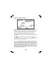
Transmitter Setup
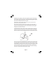
Remove both the near-end and far-end shield bonds from the test section.
Perform a battery test then with the Transmitter off, connect the Black clip
to the ground rod. Place the ground rod behind the Transmitter, away from
the faulted section, and in line with the cable path. If necessary, extend the
ground lead with the Ground Extension Cable.
Attach the Red clip to shield.
Press to turn the Transmitter on in the
Ohms mode
. Measure the fault resistance. The results are displayed in
ohms. Note that failure to disconnect the shield bonds at either the near-
end or the far-end produces a heavy fault indication.
Press
again, to select the Fault mode . For maximum fault
sensitivity, select high output level by pressing
.
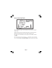
Receiver Setup
Press to turn the Receiver on.
Press to select Fault mode . Connect the Earth Contact Frame
to the accessory jack on the Receiver using the earth frame cable. Near the
location of the ground rod (about one step away), insert the frame probes
fully into the ground with the green-banded leg towards the fault and in
line with the cable path. Press
to record a fault level reference visible
in the lower left corner of display.
Page 14
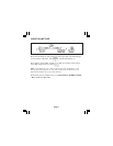
In general, when the Transmitter is set up to apply more current on the
target cable than any other cable, the cable can easily be identified because
the Receiver current reading will be highest.
Note: Since some of the signal in the cable will bleed into the earth, it is
expected that the Receiver current indication along the cable will decrease
gradually away from the Transmitter. This effect is more pronounced at
higher frequencies.