6-6
7. Check for the resistance values of the
motor’s Main and Start winding coils, as
shown in the following table. NOTE: Main
and Start winding coils must be checked at
the motor.
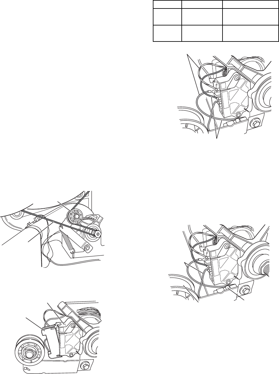
8. Check the belt switch by measuring resis-
tance between the two blue wires, while
pushing up on the belt switch pulley.
• If the resistance reading goes from in-
finity to a few ohms as pulley arm closes
the switch, belt switch is okay. If not,
replace the belt switch.
TEST #2: MOTOR CIRCUIT TEST
This test will check the wiring to the motor and
the motor itself. The following items are part of
this system:
• Harness/connection
• Thermal fuse (electric dryers only)
• Belt/belt switch
• Drive motor
• Door switch
• Electronic control board
1. Unplug dryer or disconnect power.
2. Access the electronic control board and
measure the resistance across P1-3 and
P1-4.
• If resistance across P1-3 and P1-4 is in
the range of 1 to 6 ohms, replace the
electronic control board.
• Otherwise, go to step 3.
3. Check the wiring and components in the
path between these measurement points
(refer to the Wiring Diagrams in Section 7).
4. Electric Dryers Only: Check the thermal
fuse (see TEST #3b on page 6-9).
5. Check the belt switch and drive motor.
6. Remove the white connector from the
drive motor switch.
• If the resistance at the motor is correct,
there is an open circuit between the
motor and electronic control board.
Check for a failed belt switch.
Winding
Resistance
Test Points
MAIN
2.4 - 3.6
ohms
START
2.4 - 3.8
ohms
hite Connector
Drum Belt
Belt Switch Pulley
Start Winding: Blue Wire In Back And Violet Wire
Main Winding: Blue Wire In Back And White/Orange Wire
Blue Wires
Belt Switch
Belt Switch Pulley


