– 119 –
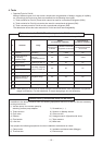
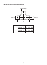
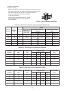
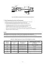
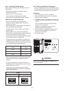
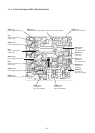
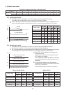
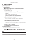
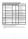
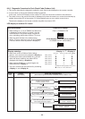
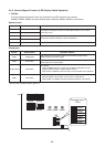
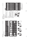
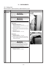
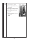
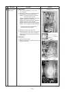
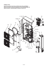
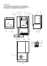
Heat exchanger Motor base
Discharge
port cabinet
Discharge
port cabinet
Bottom plateFin guard
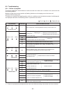
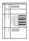
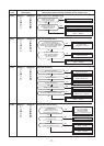
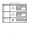
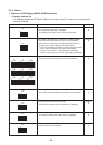
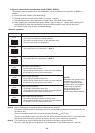
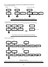
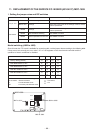
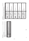
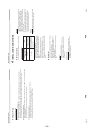
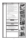
No.
2
Part name
Discharge
port cabinet
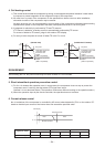
Procedure
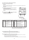
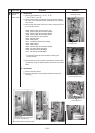
1. Detachment
1) Carry out the operation in 1. of
Q
above.
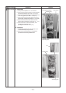
2) Remove the screws fixing the inverter assembly,
the discharge port cabinet and the partition board.
(ST1T Ø4 × 8, 4 pcs.)
3) Remove the screws for the discharge port cabinet
and the bottom plate.
(Hexagonal screw Ø4 × 10, 2 pcs.)
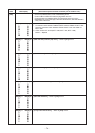
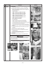
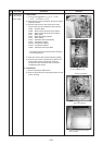
4) Remove screw for the discharge port cabinet and
heat exchanger. (ST1T Ø4 × 8, 1 pc.)
5) Remove screw for the discharge port cabinet and
the motor base. (ST1T Ø4 × 8, 2 pcs.)
6) Remove screws for the discharge port cabinet
and the fin guard.
(Hexagonal screw Ø4 × 10, 2 pcs.)
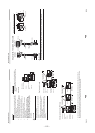
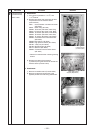
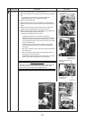
2. Attachment
1) Attach the discharge port cabinet and end board
of heat exchanger and fix with a screw.
(ST1T Ø4 × 8, 1 pc.)
2) Mount other removed screws into original
positions.
Remarks