109
Using the RM-B750
Appendixes
Appendixes
Using the RM-B750
When the RM-B750 Remote Control Unit (optional) is
connected, you can control the menu settings of this
camera and monitor the camera images on the display of
the RM-B750.
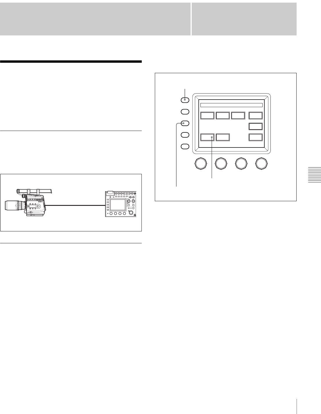
Connection
Using the remote control cable supplied with the RM-
B750, connect the CAMERA connector of the RM-B750
and the REMOTE connector of the camera.
Operating the Menu of This Camera
The menu of this camera can be displayed on the display
of the RM-B750 and be set from the RM-B750.
Settings on this camera
• Set RM [SIG] to VBS on the <MONITOR OUTPUT>
page of the USER (OPERATION) menu.
• Set VBS of CHAR to ON on the <CHAR/MARK MIX>
page of the USER (OPERATION) menu.
• Set NS MODE to LEGACY on the <700PTP
SETTING> page of the NETWORK menu.
Settings on the RM-B750
1
Press the MAINTENANCE/VF MENU button to
display the maintenance menu on the LCD/touch
panel.
2
Press [RM Config] on the touch panel to display the RM
configuration menu.
3
Press [Security] to set the unit to Engineering Mode.
4
Press [SW Setting] to change to the SW Setting display
and set the VF Menu to Control Enable.
5
Press [Exit] to cancel the menu mode.
If you press the MONITOR button, a menu page of this
camera will be displayed on the display of the RM-B750.
Pressing the MAINTENANCE/VF MENU button enables
the menus of this camera to be set from the RM-B750.
For details on the operations, refer to the Operation
Manual of the RM-B750.
CAMERAREMOTE
FUNCTION
MAINTE
NANCE
SCENE
PAINT
ALARM
PANEL
ACTIVE
MEMORY
STICK
STANDARDMONITORTEST BARS
5600K AUTO
KNEE
SKIN
DETAIL
BLACK
GAMMA
KNEE
SATURATION
CLOSE
AWB
AUTO
IRIS
IRIS/MB
ACTIVE
MASTER
BLACK
REMOTE CONTROL UNIT
EXT
IRIS
ABS
WHITE
BLACK
ABB
VTR
START/STOP
RM-B750
MONITOR
FUNCTION
VF DISP
MENU SELECT
MAINTENANCE
VF MENU
SCENE
CANCEL
PA IN T
ENTER
BRIGHT
CONTRAST
Auto
Setup
Camera
Config
RM
Config
LCD
Memory
Stick
Super
Motion
Adjusting File
Maintenance Menu
MONITOR button
MAINTENANCE/VF MENU button
MAINTENANCE menu
[RM Config]
