:..
.;..
..~..
e
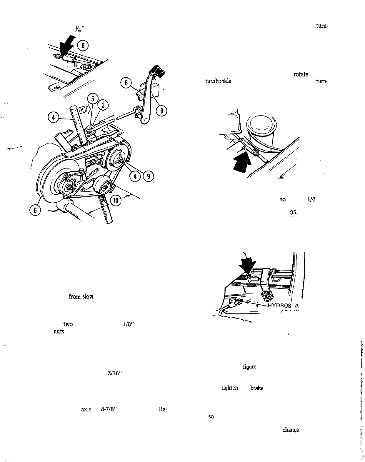
FIGURE 23
7. Replace the spark plug wire and start the engine. Move
the control lever from slow to fast and check your adjust-
ments. Repeat steps 1 through 6 if not correct.
8. Place the variable speed lever in the high (7) position
and adjust the
two
locknuts so there is
l/8”
clearance be-
tween the
nuts and the rod guide. To loosen the two nuts,
hold the forward one while turning the rear one counter-
clockwise. Tighten the nuts securely against each other af-
ter completing the adjustment. See figure 23.
9. With the variable control in the high (7) position ad-
just the belt guard to obtain a
3116”
clearance between
the belt and the guard. See figure 23.
10. Loose” the nut at inside of the clutch idler and adjust
belt stop so the distance between its front edge and the
forward side of the axle is
8-718”
See figure 23.
Re-
tighten the nut and check the adjustments.
Hydrostatic Transmission: If the tractor tends to creep
(move slightly forward or backward) when the hydrostatic
speed control lever is in the Neutral position, the turn-
buckle may need adjusting. See figure 24. To adjust, place
the control lever in the neutral position. THE HYDRO-
STATIC LOCKOUT AT THE REAR OF THE TRACTOR
MUST BE IN THE “DRIVE” POSITION. Loosen the nuts
at each end of the turnbuckle. Start the engine. If the trac-
tor creeps forward turn the top of the turnbuckle toward
the tractor. If the tractor creeps backward,
rcztate
the top
of the turnbuckle away from the tractor. When the tum-
buckle is adjusted so the tractor will not creep, tighten the
nuts at each end.
FIGURE 24
The tractor clutch should be adjusted
so
there is I/8 inch
clearance between the nuts and the rod guide when the
clutch is completely released. See figure
?;F.
Loosen the
nuts by holding the forward one while turning the rear one
counterclockwise. Retighten the nuts against each other
when the adjustment has been completed.
i
TIC BRAKE
ADJUSTMENT
FIGURE 25
1
Brake Adjustment, Foot Pedal: The foot pedal brake ad-
justment is at the right rear of tractors equipped with hy-
drostatic transmissions and at the left rear of those with
the variable speed. See
f@re 26. To adjust, it is necessary
to loosen the two nuts. Hold the front one and turn the
rear nut counterclockwise to loosen. Turn the forward nut
clockwise to
,tighten the
,breke
and counterclockwise, to
loosen. Tighten only enough so the brake will stop the
tractor. Further tightening of the brake may cause the
brake to drag when moving the tractor. When the brake is
adjusted
so
it works properly, tighten the rear nut up a-
gainst the forward one to lock them in place. Hold the for-
ward one with a wrench so you do not
change
the adjust-
ment when tightening the nuts together.
13


