Pelco Manual C221M-C (6/03) 7
ᕦ Prepare Monitor for Installation
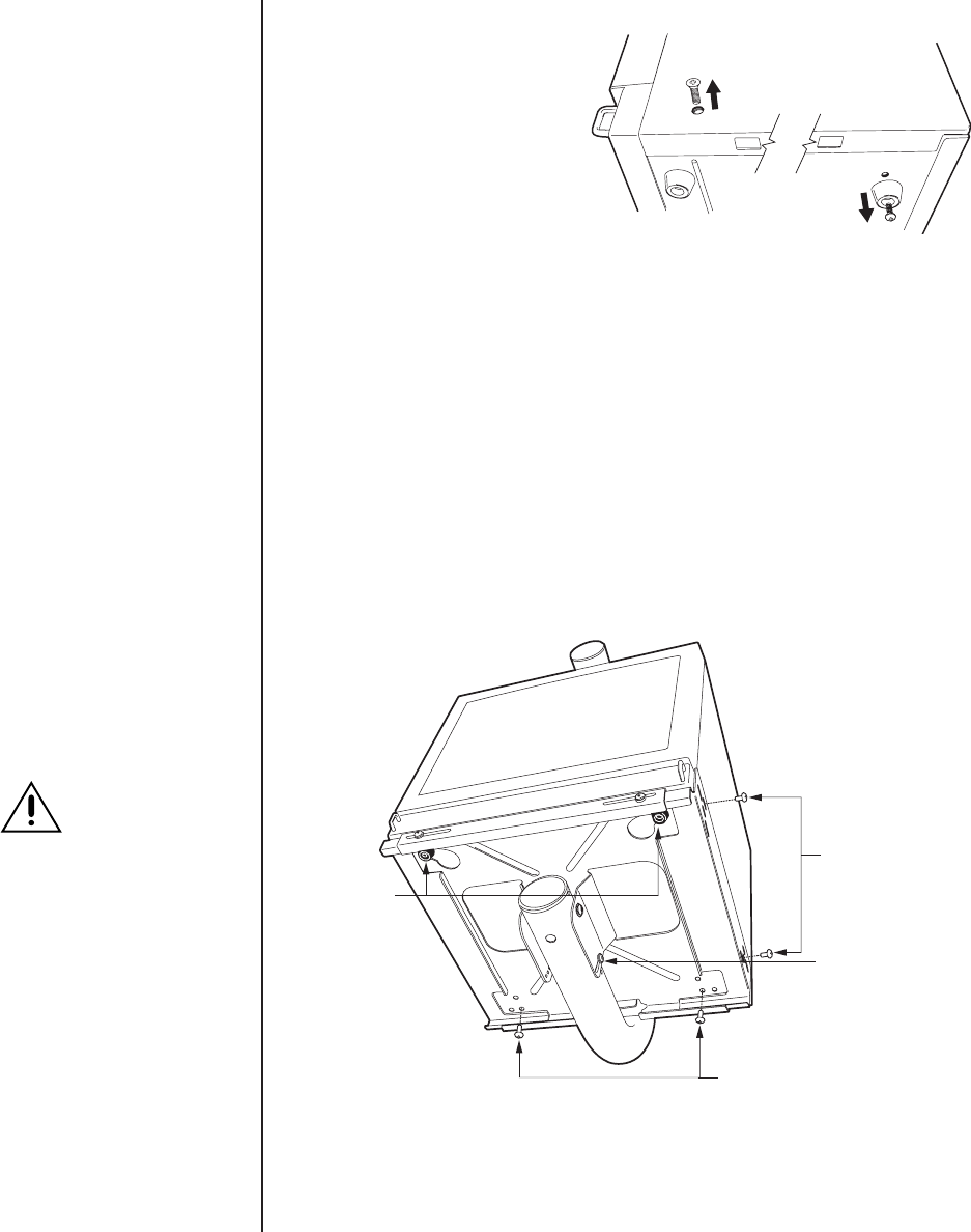
Refer to Figure 6 and remove the
monitor’s back feet and side screws.
SECURE BOTH
SIDES OF MONITOR
WITH HARDWARE
SECURE BOTH
SIDES OF MONITOR
WITH HARDWARE
FRONT FEET
OF MONITOR
NOTE: THE POSITION OF THE FRONT FEET AND BACK FEET
MOUNT HOLES WILL VARY WITH MONITOR MODEL.
MONITOR RACK
ANGLE ADJUSTMENT
01121
CAUTION:
Secure the mount
rack before install-
ing the monitor.
NOTE:
Reattach the back
feet to the monitor if it is
used in an installation other
than described in this
manual. Only use the follow-
ing hardware to attach feet:
PMC21A
Two #8 x .50-inch Phillips
pan head screws and fin-
ishing washers (supplied,
see page 4)
PMCS19A
Two M4 x 12 mm Phillips
pan head screws and fin-
ishing washers (supplied,
see page 4)
Do not use any other type of
hardware to attach the back
feet to the monitor.
Figure 6. Prepare Monitor
ᕧ
Install Monitor
a. Verify that the monitor rack is level. Place the monitor onto the monitor rack. For
proper installation, the front feet of the monitor should be in the holes in the front of the
rack. Refer to Figure 7.
b. Use the following hardware to secure the back of the monitor to the rack:
PMCS19A - Two M4 x 12 mm, black, Phillips, pan head screws (provided).
PMC21A - Two #8 x .50-inch, black, Phillips, pan head screws (provided).
c. Adjust the sides of the rack to fit against the sides of the monitor. Use the following
hardware to secure the monitor to the rack sides:
PMCS19A - Use the two M6 x 12 mm, Phillips, pan head screws and washers (provided).
PMC21A - Four #8 x .50-inch, black, Phillips, pan head screws (provided).
Figure 7. Install Monitor


