16 C3662M (6/08)
DS DESKTOP INSTALLATION
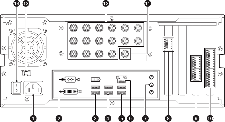
To install DS Desktop, refer to Figure 9 for 9-input or 16-input systems, or Figure 10 for 4-input systems, and then complete the following steps:
1. Plug the power cord into the power connector
ì.
2. Plug a monitor into a monitor connector î and its power cord into an electrical outlet. The top connector is for a VGA monitor, and the
bottom connector is for a DVI monitor.
3. Plug the USB keyboard into a USB connector
ï.
4. Plug the USB mouse into a USB connector
ñ.
5. Plug a USB printer into a USB connector ó.
6. Connect the network port r to a network switch using Cat5 cable.
7. Plug PC speakers into the line out connector s.
8. Item t is the COM5 connector, which is used with RS-422 PTZ cameras. Refer to PTZ Installation on page 29 for installation details.
9. Item
u is the audio connector bracket. From top to bottom are audio inputs 1–4, audio outputs 1–4, and four grounds.
10. Item
~í shows the connector for the 16 digital inputs and alarm output. Wire your alarm triggers into the input trigger block and connect
the signal ground to a GND pin. Wire an alarm device to AO+ and AO–.
11. Item ~â is a multicamera video output that can be connected to an analog monitor.
12. Connect cameras to the camera inputs ~ä.
13. Select the correct input voltage for your area using the input voltage switch ~ã.
14. Plug the power cord into an electrical outlet and turn on the power switch ~å .
15. To turn on the server, use the power switch on the front panel of the unit.
Figure 9. Rear Panel of 9- and 16-Input DS Desktop
NOTE: The number of camera input BNCs varies based on the model number.
INTPUT 14 INTPUT 15 INTPUT 16 OUTPUT 1INPUT 13
INPUT2INTPUT1
INPUT 10INPUT 9INPUT 8INPUT 7
INPUT 6INPUT 5INPUT 4INPUT 3
INPUT 2INPUT 1
115


