English
10 1. INTRODUCTION
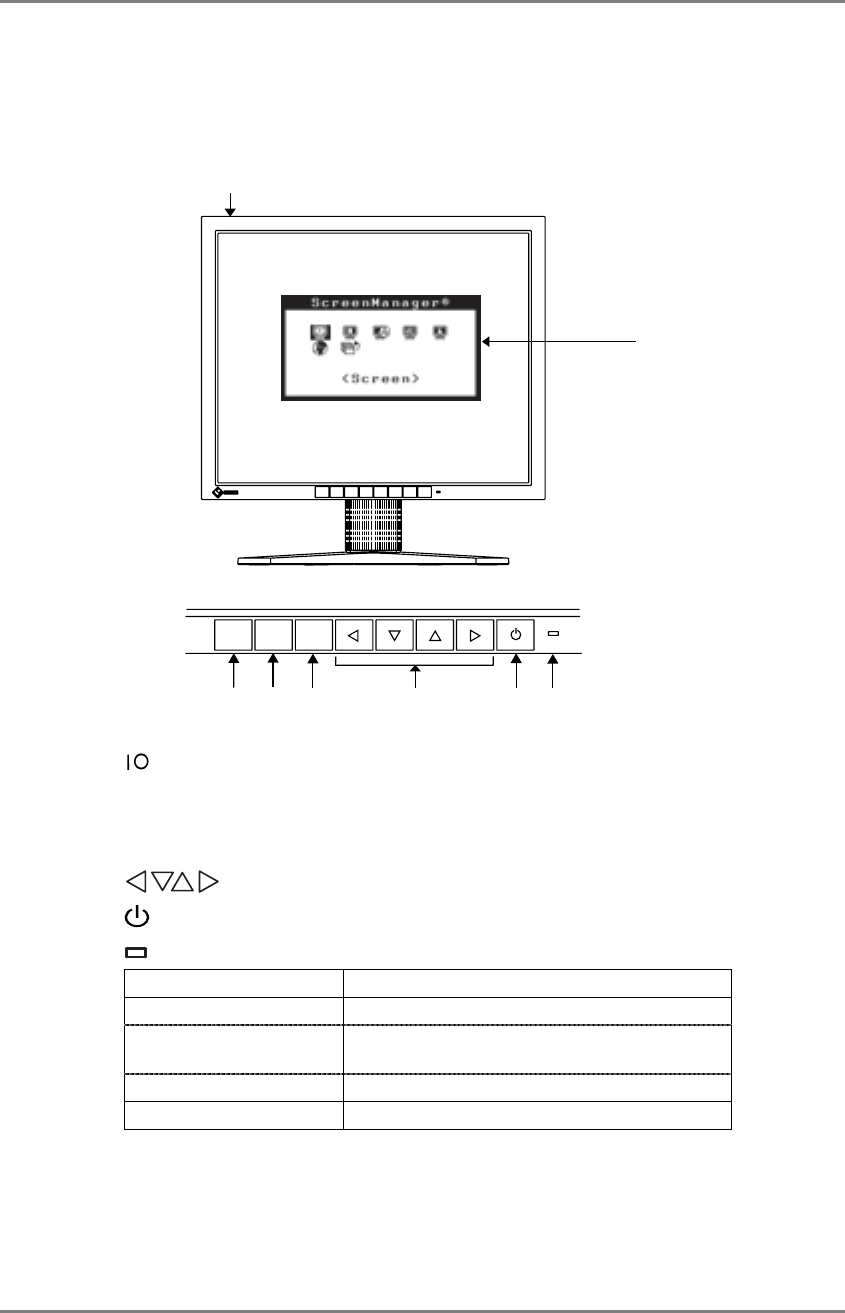
1-3. Controls & Connectors
Front
ENTERAUTO
SIGNAL
1 - 2
(4)
(2)
(5)
(6)
(3)
(7)
(8)
(1)
(1) ScreenManager
(2)
Main Power Switch
(3) SIGNAL 1-2 Signal selection button (Color/Monochrome)
*1
(4) AUTO Auto Adjustment Button
(5) ENTER Enter Button
(6)
Control Buttons (Left, Down, Up, Right)
*2
(7)
Power Button
(8)
Power Indicator
*3
Green Operation
Orange Power saving
Flashing orange (2 times
for each)
Power save mode Digital only
Flashing orange slowly Power is off (Main power is on)
Off Power off
*1
Select color or monochrome for the graphics board of use (p.14).
*2
These buttons are changed to Down, Right, Left, Up in case of selecting “Portrait”
for <Orientation> of ScreenManager <Others> (p.17).
*3
Green lighting, when the screen is displayed (Operation mode), is made to non-light,
see page 17.
Regarding the power indicator for the off timer, see page 18.
Control Panel


