8
Getting Started
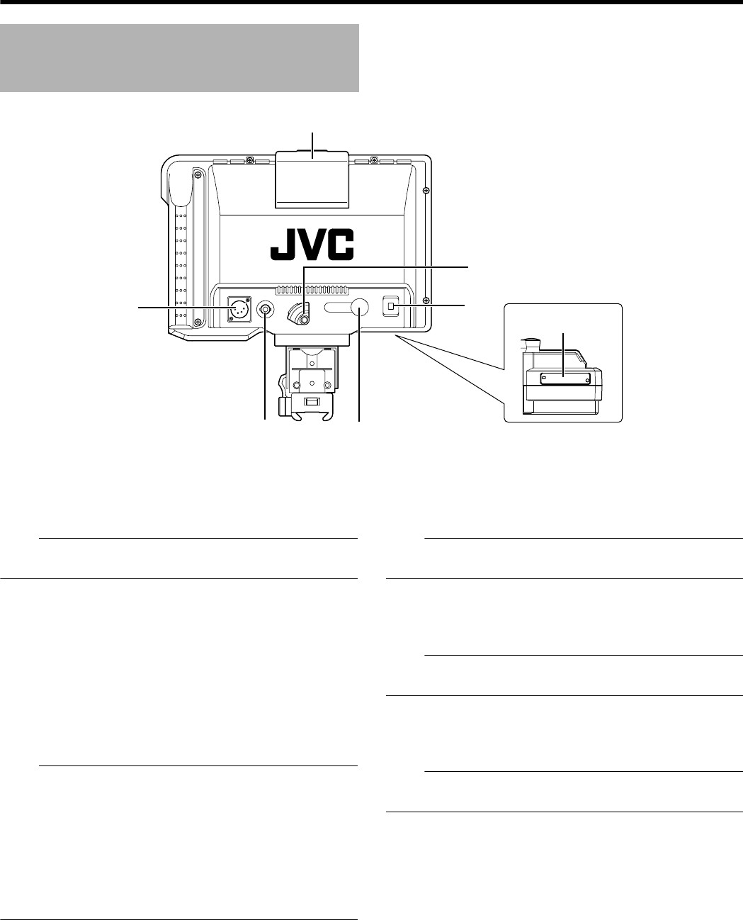
I [TALLY] Switch
This turns ON/OFF the TALLY lamp M.
ON : TALLY is enabled.
OFF : TALLY is disabled.
Note:
● The TALLY lamp H at the screen operates regardless of this
switch.
J [DC INPUT] Terminal (XLR type, 4-pin)
This product can operate by connecting to an external power
supply of DC 12 V. (When this product is connected to
KA-HD250U, this terminal does not have to be connected to an
external power supply.)
K [RETURN] Input Terminal
This is an input terminal for composite video signals or
component (Y only) signals. It connects the return video
signals.
Note:
● Select the type of return video signals from the [RET VIDEO]
item on the [VIDEO FORMAT] menu screen of this product.
(A Page 15)
● B&W screen will be displayed even when composite video
signals are input.
● During return video signal display, status display other than
[CAMERA NAME] will be AOFFB.
● The above feature may not function depending on the
version of the camera’s software. For details, please consult
JVC’s authorized dealers.
L [VF CABLE] Input Terminal
Connect this terminal to the KA-HD250U VF output terminal
(20-pin) with the provided VF cable.
M TALLY Lamp
This displays the monitor status of the input screen in red.
Only when Tally PGM (Program) signals are input, the lamp
lights up in red.
Note:
● Use [TALLY] switch I to turn ON/OFF the display function of
this lamp.
N VF CABLE HOLDER
This holder clamps down the provided VF cable when
connecting the cable to the input terminal.
Note:
● Be sure to secure the VF cable with the holder as it prevents
the cable from slipping during connection. (A Page 9)
O DIP Switch (A Page 17)
Some functions can be specified according to the usage of
individual users.
Note:
● Use the factory settings when connecting to the GY-HD250U
with KA-HD250U system.
Names and Functions of Parts
(Rear)
DC INPUT
RETURN
VR CABLE TALLY
ON
OFF
I
L
K
M
N
O
VF-HP840U_EN.book Page 8 Thursday, January 17, 2008 2:48 PM


