ASSEMBLY INSTRUCTION
Tools Required for Assembling the Equipment: Two Adjustable Wrenches and Allen Wrench
NOTE: It is strongly recommended that two or more people assemble this machine to avoid
possible injury.
STEP 1 (See Diagram 1)
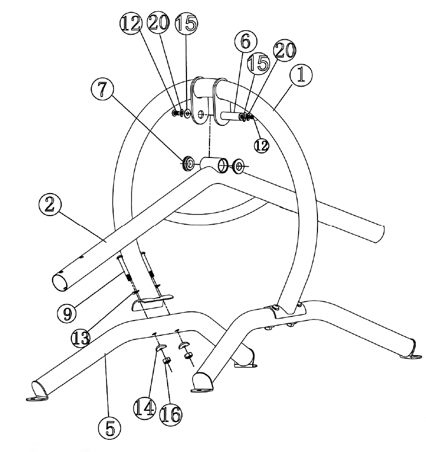
A.) Place the two Base Stabilizers (#5) on a flat surface. Attach one end of the Main Frame (#1) to a
Base Stabilizer. Secure it with two M10 x 2 5/8” Allen Bolts (#9), two Ø ¾” Bent Washers (#13),
two Ø 1 1/8” Bent Washers (#14), and two M10 Aircraft Nuts (#16).
B.) Repeat the same procedure to install the other Base Stabilizer.
C.) NOTE: Soliciting help from another person is strongly recommended for this step. Place the
Pivot on the Swing Frame (#2) in between the brackets on the Main Frame. Attach a Bushing
(#7) to each end of the Bracket.
D.) Align the holes then insert the Axle (#6) through the holes and secure it with one M10 x 5/8”
Allen Bolt (#12), one Ø ¾” Lock Washer (#20), and one Ø 1” Washer (#15) on each end of the
Axle. Do not over tighten the Bolts. Make sure the Swing Frame is able to swing smoothly.
DIAGRAM 1
6


