EN Internal assemblies 87
Pressure Roller
1 Remove Printer Covers, Delivery Assembly (Figures 6-9 and 6-10), Fuser Pressure Plate (Figure
6-11), and Heating Element (Figures 6-13 through 6-15).
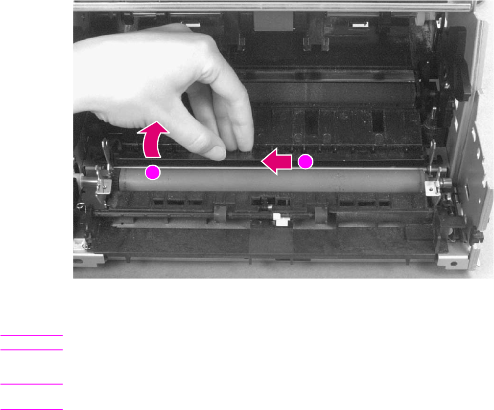
2 Remove the Pressure Roller guide by lifting the edge (Figure 6-16, callout 1) and then rolling it
gently backward (Figure 6-16, callout 2).
Figure 6-16 Pressure Roller Guide removal
3 Lift the right end of the Pressure Roller up and out of the printer chassis.
Note The right end of the Pressure Roller is greased.
4 The left side will follow easily with the Pressure Roller gear still attached.
Note When reinstalling the Pressure Roller, apply a drop of grease to the grounding plate on the right side
of the shaft. (Refer to Chapter 8 for a part number.)
1
2
Service.book Page 87 Thursday, September 14, 2000 11:15 AM


