Principles of Operation
Control Circuit Operation
The control circuit consists of two circuit boards: the CO94 MAIN (main control circuit board) and
the CO94 PNL (control panel circuit board). This section describes the operation of these boards.
Control Circuit Operation Overview
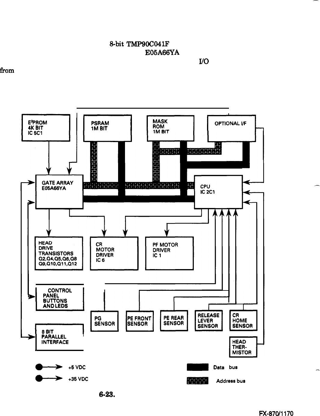
The CPU on the CO94 MAIN is an 8-bit
TMP9OCO41F
microprocessor (9.83 MHz). It oversees
control of all the components of the printer. The E05A66YA gate array contains various memory
management functions that control the memory assignment and
J/O
areas. The output signals
fkom
each detector are sent to the analog input port of the CPU.
The signals from the control panel
are sent to the gate array, which in turn, sends LED signals to the control panel. The two motors
(CR and PF) are controlled by signals sent from the stepping motor control port of the CPU.
Figure
6-23 shows the control circuits in block diagram form.
I
I
-I-
I
E’PROM
I
I
I
PSRAM
4K
BIT
1M
BIT
I
I
‘-1
pzG=L
MASK
ROM
-.*
-.-
1
CONTROL
1
I
w
I
PANEL
BUlTONS
AND
LEDS
I
I
+j
~i%k%E
1
s
+6VDC
m
Data
bus
w
+36VDC
Address
bus
Figure! 6-23. Control Circuit Block Diagram
Epson
FX-87W1170
-
-
6-22


