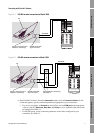
44 Micro Motion
®
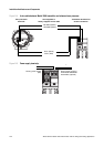
Model 1500 Transmitters with the Filling and Dosing Application
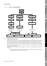
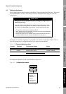
Optional Transmitter Configuration
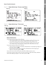
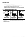
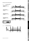
Example 2
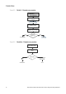
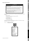
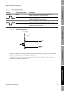
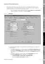
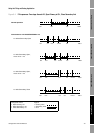
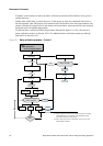
Configuration:
• Flow direction = Reverse
• mA output: 4 mA = 0 g/s; 20 mA = 100 g/s
(See the second graph in Figure 6-1.)
As a result:
• Under conditions of forward flow or zero flow, the mA output level
is 4 mA.
• Under conditions of reverse flow, up to a flow rate of 100 g/s, the
mA output level varies between 4 mA and 20 mA in proportion to
the absolute value of the flow rate.
• Under conditions of reverse flow, if the absolute value of the flow
rate equals or exceeds 100 g/s, the mA output will be proportional
to the absolute value of the flow rate up to 20.5 mA, and will be
level at 20.5 mA at higher absolute values.
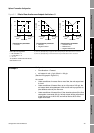
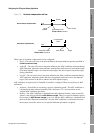
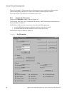
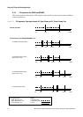
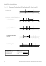
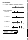
Example 3
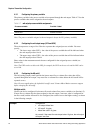
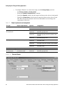
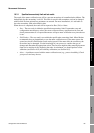
Configuration:
• Flow direction = Forward
• mA output: 4 mA = –100 g/s; 20 mA = 100 g/s
(See the first graph in Figure 6-2.)
As a result:
• Under conditions of zero flow, the mA output is 12 mA.
• Under conditions of forward flow, up to a flow rate of 100 g/s, the
mA output varies between 12 mA and 20 mA in proportion to (the
absolute value of) the flow rate.
• Under conditions of forward flow, if (the absolute value of) the flow
rate equals or exceeds 100 g/s, the mA output is proportional to
the flow rate up to 20.5 mA, and will be level at 20.5 mA at higher
flow rates.
• Under conditions of reverse flow, up to a flow rate of 100 g/s, the
mA output varies between 4 mA and 12 mA in inverse proportion
to the absolute value of the flow rate.
• Under conditions of reverse flow, if the absolute value of the flow
rate equals or exceeds 100 g/s, the mA output is inversely
proportional to the flow rate down to 3.8 mA, and will be level at
3.8 mA at higher absolute values.