


295421-YTG-B-0707
4 Unitary Products Group
ACCESSORIES
Refer to Price Manual for specific model numbers.
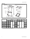
VERTICAL SUSPENSION KIT - The suspension kit is
designed to be used with all sizes of fan coil units whenever
the application requires vertical suspension of the unit.
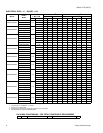
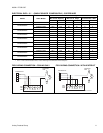
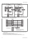
ELECTRIC HEATERS - Models shown under Electrical Data
include sequencers and temperature dual limit switches for
safe, efficient operation. Circuit breakers are provided where
shown.
BOLT-ON THERMAL EXPANSION VALVE - TXV kits are
available for enhanced efficiency. These fan coil units have
factory installed TXV’s.
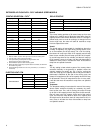
LIMITATIONS
These units must be wired and installed in accordance with
all national and local safety codes. Voltage limits are as fol-
lows:
Air flow must be within the minimum and maximum limits
approved for electric heat, evaporator coils and outdoor units:
Normal Operating voltage Range
1
1. Utilization range “A” in accordance with ARI Std. 110.
187-253
Entering Air Temperature Limits
Wet Bulb Temp. ºF Dry Bulb Temp. ºF
Min. Max. Min. Max.
57 72 65 95
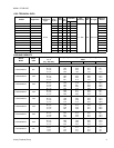
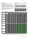
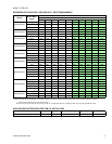
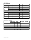
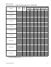
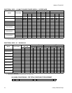
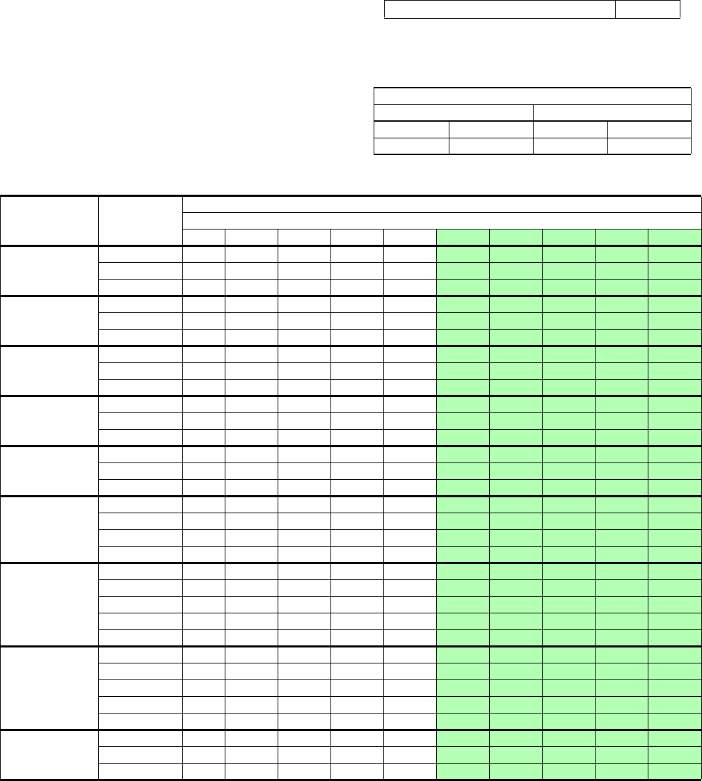
EXTENDED AIRFLOW DATA
1
FOR 230 VOLT - HEAT PUMP MODELS
1. Includes Return Air Filter and Largest Electric Heater.
All F*FP series air handler units are UL Listed up to 0.50" w.c. external static pressure, including air filter, wet coil, and largest KW size heater.
Models
Blower Motor
Speed
230 Volt
CFM @ External Static Pressure - IWC
0.10 0.20 0.30 0.40 0.50
0.60 0.70 0.80 0.90 1.00
F4FP024H06T2*
High 950 910 865 835 775
730 662 590 502 400
Med 845 815 785 745 705
654 594 524 439 344
Low 650 630 605 575 540
508 450 383 285 158
F4FP030H06T2*
High 1,270 1,210 1,150 1,085 1,015
946 862 769 645 502
Med 1,050 1,040 995 930 855
804 714 624 494 364
Low 855 820 780 735 680
624 550 447 333 190
F4FP036H06T2*
High - 1,310 1,250 1,175 1,120
1,053 983 894 779 645
Med 1,200 1,150 1,100 1,040 985
933 879 795 711 587
Low 1,060 1,015 970 925 860
809 740 661 572 453
F4FP040H06T2*
High 1,270 1,210 1,150 1,085 1,015
946 802 769 645 502
Med 1,050 1,040 995 930 855
804 714 624 494 364
Low 855 820 780 735 680
624 550 447 333 190
F4FP042H06T2*
High - 1,575 1,500 1,420 1,350
1,273 1,192 1,102 996 871
Med 1,460 1,395 1,330 1,260 1,190
1,125 1,052 960 842 695
Low 1,250 1,200 1,155 1,100 1,050
1,001 931 851 751 631
F4FP045H06T2*
High 1,575 1,535 1,475 1,390 1,310
1,245 1,147 1,030 897 735
Med High 1,375 1,315 1,255 1,185 1,110
1,040 944 848 732 606
Med Low 1,210 1,160 1,110 1,050 980
921 844 737 640 533
Low 1,035 990 940 890 825
770 698 616 524 432
F5FP048H06T2*
High 2223 2158 2090 2029 1929
1861 1788 1679 1594 1501
Med High 1948 1904 1801 1815 1777
1741 1681 1618 1539 1453
Med 1741 1690 1649 1606 1564
1516 1476 1436 1387 1353
Med Low 1499 1454 1415 1370 1328
1269 1228 1191 1132 1093
Low 1286 1233 1177 1142 1092
1039 987 960 888 842
F5FP060H06T2*
High 2195 2145 2070 2008 1920
1852 1754 1663 1570 1462
Med High 1938 1899 1873 1824 1791
1724 1679 1603 1521 1420
Med 1726 1681 1641 1607 1560
1517 1485 1433 1402 1349
Med Low 1525 1483 1441 1383 1356
1291 1253 1208 1169 1123
Low 1306 1254 1204 1160 1114
1061 1008 980 914 876
F4FV060H06T2*
High 2,285 2,195 2,105 2,015 1,950
1,845 1,770 1,685 1,590 1,485
Med. 2,125 2,020 1,910 1,805 1,705
1,597 1,491 1,386 1,280 1,175
Low 1,655 1,605 1,550 1,500 1,450
1,398 1,326 1,245 1,153 1,052
NOTE: Air flow data shown above 0.50” W.C. external static pressure is for REFERENCE ONLY. Maximum allowable external static when electric heat is used is
limited to 0.50” W.C. Maximum allowable external static pressure may also be limited by minimum CFM requirements for proper Heat Pump operation.