


2
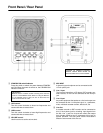
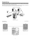
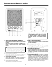
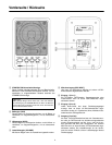
Front Panel / Rear Panel
CAUTION: TO PREVENT ELECTRIC
SHOCK, MATCH WIDE BLADE OF
PLUG TO WIDE SLOT, FULLY INSERT.
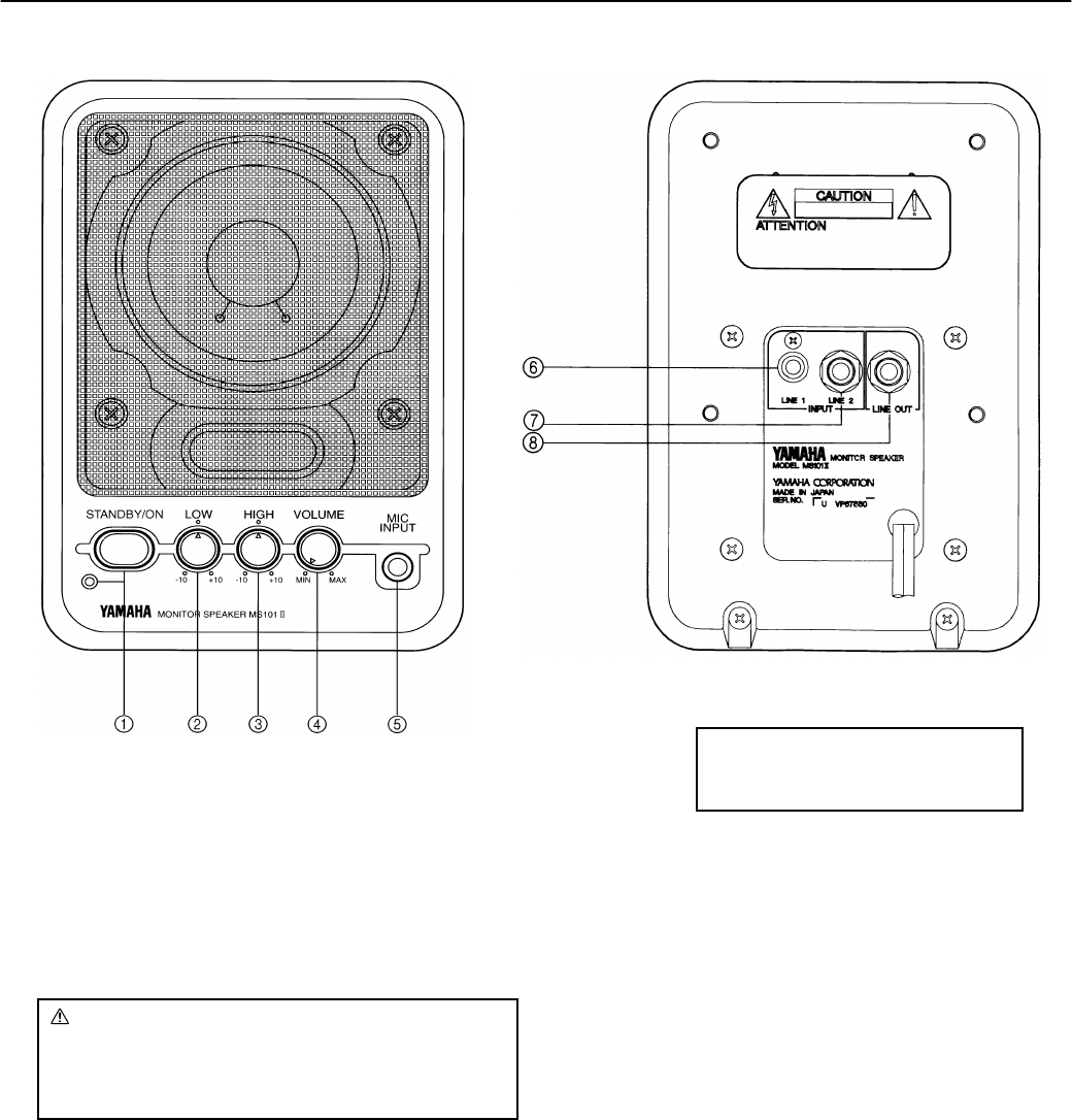
1
STANDBY/ON switch/indicator
Press this switch to switch the power between STANDBY
and ON. When the power is turned on, the STANDBY/ON
indicator comes on.
2
LOW control
Turn this control clockwise to boost low frequencies and
counterclockwise to reduce them.
3
HIGH control
Turn this control clockwise to boost high frequencies and
counterclockwise to reduce them.
4
VOLUME control
Use this control to set the volume level.
5
MIC INPUT
A dynamic type microphone can be connected to this
1/4 inch phone jack.
6
Line 1 Input
The line level output from a CD player, DAT recorder, cas-
sette recorder, or VCR can be connected to this RCA pin
jack.
7
Line 2 Input
Any audio equipment that produces a line level output can
be connected to this 1/4 inch phone jack, i.e., synthesizer,
mixer, multitrack cassette recorder, effects unit, etc.
8
Line Out
A cassette recorder or DAT recorder can be connected to
this 1/4 inch phone jack for recording. Input signals from
the Mic, Line 1, and Line 2 inputs are mixed, then output
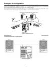
here. Another MS101
II
can be connected to this jack for
parallel operation. The front panel volume knob doesn’t
effect the volume level of this line out.
CAUTION:
A small amount of electric current is flowing even when the
power is in the STANDBY mode. When not using the MS101
II
for an extended period of time, be sure to discon-nect the
power cord from the AC outlet.