


E-4
PREPARATIONS
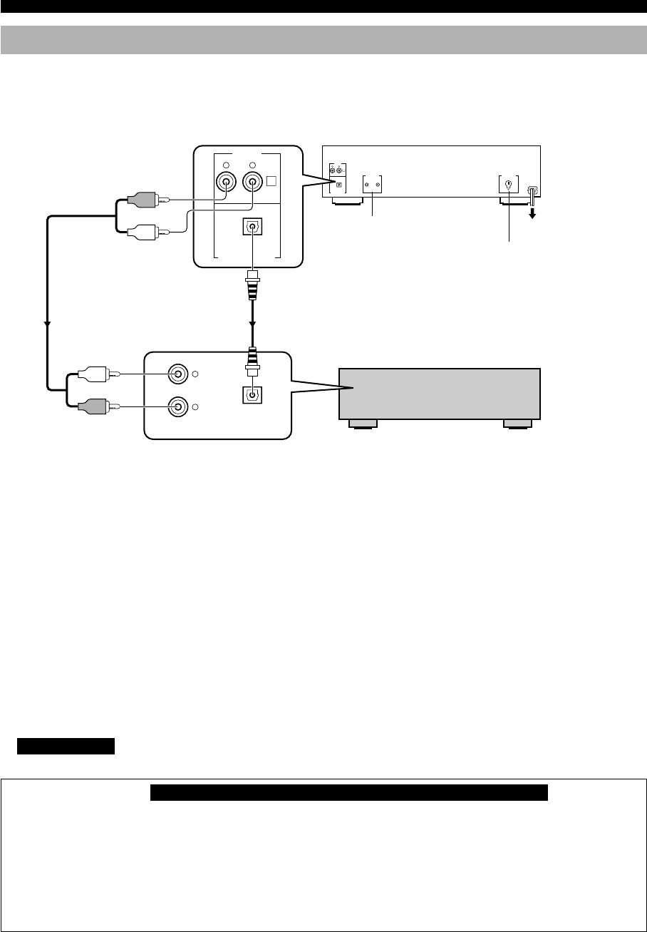
Connections
Never plug in this unit and other components until all connections are completed.
• Before making any connections, switch OFF the power to the unit and the amplifier or other components.
• Connections should be made to the correct input terminals of the amplifier or other components.
• If the placement of this unit causes noise in other equipment, such as a tuner, separate them from each other.
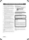
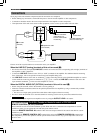
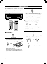
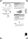
Choose one of the ways listed below to connect this unit to your amplifier.
When the LINE OUT (analog) terminals of this unit are used (1)
• Be sure that the left (L) and right (R) LINE OUT terminals are connected to the corresponding (left and right) terminals of
the amplifier or other components.
• Connect the LINE OUT terminals to the “CD” (or “AUX”) terminals of the amplifier. For additional details concerning
these connections, refer to the operation instructions for the amplifier being used.
• The LINE OUT terminals of this unit are numbered !. When connecting this unit with a YAMAHA amplifier or receiver
whose terminals on the rear panel are numbered as !, @, #, etc., connect the LINE OUT terminals of this unit to the
input terminals numbered ! on the rear of the amplifier or receiver.
When the DIGITAL AUDIO OUT (OPTICAL) terminal of this unit is used (2)
• Before using this terminal, remove the terminal’s cover by pulling it.
• Make the connection from this terminal to the optical input terminal of an amplifier by using a commercially available
optical fiber cable.
* Be sure to use a high quality optical fiber cable. Other cables might not function correctly.
• Be sure to attach the terminal cover when this terminal is not being used in order to protect the terminal from dust.
• CDC-685 only
Set the level of signals output into an amplifier to max. by using the OUTPUT LEVEL –/+ buttons.
For Custom Installer For U.S.A., Canada and Australia models of CDC-685 only
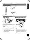
REMOTE CONTROL (IN, OUT) terminals
These terminals are used for custom installation system. When this unit is connected to the components for custom
installation system, you can operate this unit with the system remote control.
Connect the REMOTE CONTROL IN terminal of this unit to the output terminal of the central controller for custom
installation system.
By connecting the REMOTE CONTROL OUT terminal of this unit to the REMOTE CONTROL IN terminal of the
other component, you can also operate it with the system remote control. In this way, up to 6 components can be con-
nected in series.
R L
1
LINE OUT
DIGITAL AUDIO OUT
OPTICAL
REMOTE CONTROL
IN OUT
VOLTAGE SELECTOR
DIGITAL IN
ANALOG IN
CD
OPTICAL
R
L
R L
1
LINE OUT
DIGITAL AUDIO OUT
OPTICAL
To AC outlet
VOLTAGE SELECTOR
(General model only)
REMOTE CONTROL
(CDC-685 U.S.A.,
Canada and Australia
models only)
2 Optical fiber cable
(not included)
1 Pin cable
(included)
Amplifier