


Controls and Functions
XMV4280/XMV4140 Owner’s Manual
9
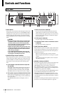
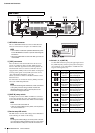
t [SELECT] buttons/indicators A/B/C/D
Use these buttons to select the output channel that you want
to control. The indicator of the selected channel will light.
By using these in conjunction with the [FUNCTION] button,
you can change the parameter that is controlled by the
encoder. Refer to “List of Front Panel Operations” (page 20).
When the [PANEL LOCK] indicator is lit, front panel opera-
tions are locked, and output channel operations are not possi-
ble. Defeat the lock if you want to perform these operations.
y Display
This is a 3-digit 7-segment display that shows information
such as the attenuator value of the selected channel.
u Encoder
This encoder is used to edit parameters. For details on the
available parameters, refer to “List of Front Panel Opera-
tions” (page 20).
When the [PANEL LOCK] indicator is lit, front panel opera-
tions are locked, and settings cannot be edited. Defeat the
lock if you want to perform these operations.
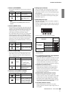
i [MUTE] indicators A/B/C/D
When you mute an output channel by operating the unit
itself or by operations via the [REMOTE] connector or the
editor, the indicator of the corresponding channel will light
yellow. When the power is turned on, the output signal will
also be muted and the indicator will blink yellow until audio
starts to be output.
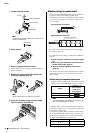
o [MUTE] button
By holding down the [MUTE] button and pressing the
[SELECT] button, you can switch muting on/off for the
channel selected by the [SELECT] button. When muting
turns on, the [MUTE] indicator will light.
When the [PANEL LOCK] indicator is lit, front panel opera-
tions are locked, and channel mute operations are not possi-
ble. Defeat the lock if you want to perform these operations.
!0 [POWER] indicator
This will light when the power supply is turned on by the
power switch (q).
It will blink when the unit is switched to standby mode via
the [REMOTE] connector or the editor.
!1 [ALERT] indicator
This will blink or light when an abnormality occurs in the
unit.
If this is blinking, note the indication in the display and refer
to “Alert Numbers and Content” (page 24).
If it is lit, stop operating the unit. After a time, the indicator
will change to blinking, and an alert number will appear in
the display.
!2 [NETWORK] indicator
This will light green if the XMV is in a linked state with an
external device via the NETWORK connector. It will blink
while data is being communicated.
!3 [YDIF] indicator
This will light green when the [YDIF] connector is con-
nected normally and a valid word clock is being input.
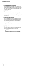
!4 [PANEL LOCK] indicator
!5 [FUNCTION] button
Use this to check or change the operating mode of the
XMV’s front panel. For details on how to perform front
panel operations, refer to “List of Front Panel Operations”
(page 20).
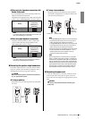
!6 Cooling vent
Located behind the vent is a variable speed cooling fan that
draws air in from the front and exhausts it through the rear.
The fan speed will automatically vary according to the tem-
perature.
Please be sure that you do not block the air intakes or
exhaust vents. You should also clean the air intakes and
exhaust vents regularly. If the air intakes are clogged with
dust or debris, the amplifier will overheat, which may result
in the amplifier shutting down.
NOTE
Even if muting is off, this indicator will blink when the protec-
tion circuit has operated to mute the output.
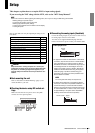
Indicator Status
Lit Front panel operations are locked.
Unlit Front panel operations are not locked.
Blinking
Lock is temporarily defeated. When the
XMV is restarted, it will be in a locked
state, and the indicator will light.
NOTE
Lock will be temporarily defeated if you press the [FUNC-
TION] button and the [SELECT] A button.