


9
CONNECTIONS
SETUP
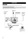
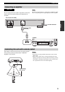
Do not connect this unit or other components to the main
power until all connections between components are
complete.
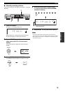
Be sure to connect the left (“L”) and right (“R”) LINE OUT jacks
to the corresponding (left and right) input jacks of the amplifier.
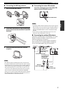
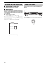
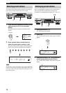
This unit has a remote control sensor. It receives signals
from a remote control provided with a YAMAHA
amplifier or AV receiver.
• Do not place any large obstacles between the remote control
and this unit.
• If the remote control sensor is directly illuminated by strong
lighting (especially an inverter type fluorescent lamp), you may
not be able to control this unit using the remote control. In this
case, reposition this unit to avoid direct lighting.
Connecting an amplifier
CAUTION
Note
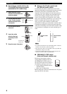
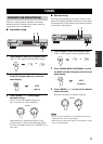
FM ANT FREQUENCY STEP
FREQUENCY STEP
FM 100kHz 50kHz
FM 100kHz 50kHz
AM 10kHz 9kHz
AM 10kHz 9kHz
LINE OUT VOLTAGE
VOLTAGE
SELECTER
SELECTER
220V-240V
220V-240V
110V-120V
110V-120V
75Ω UNBAL
AM ANTGND
R L
2
STANDBY
/ON
STANDBY
INPUT
PHONES SPEAKERS BASS
5
1
4
2
3
5
1
4
2
3
A
POWER
ON
OFF
ON
OFF
AUX MD TAPE CD/DVD TUNER PHONO PURE DIRECT CD/DVD DIRECT AMP
B
+
–
TREBLE
5
1
4
2
3
5
1
4
2
3
+
–
BALANCE
5
1
4
2
3
5
1
4
2
3
TUNER
PHONO
TAPE
MD
AUX
R
L
LOUDNESS REC OUT
VOLUME
7
–
30dB
FLAT CD/DVD
10
9
5
6
1
4
2
3
CD/DVDPHONO TUNER
POWER
STANDBY
MD
TAPE AUX
+
–
u
d
DISPLAY
A/B
REC
DISC
DIR A
p
DIR B
A/B/C/D/E
PRESET
VOLUME
TAPECD
w
e
f
b
s
a
TUNER
LR
LR
To an AC wall outlet
Audio pin cable
(included)
Amplifier
This unit (U.S.A. model)
Controlling this unit with a remote control
FREQ/TEXT
FREQ/TEXT
EON
EON
MODE
MODE
PTY SEEK
PTY SEEK
START
START
FM/AM EDIT
MAN'L/AUTO FM
MEMORY
TUNING MODE
TUNING
hl
POWER
A/B/C/D/E
23456781
AUTO/MAN'L
30
30
Approximately
6 m (19.7 ft)
Notes