IMPORTANT!
Please record the serial number of this
unit in the space below.
Model:
Serial No.:
The serial number is located on the rear
of the unit.
Retain this Owner’s Manual in a safe
place for future reference.
WARNING
TO REDUCE THE RISK OF FIRE OR
ELECTRIC SHOCK, DO NOT EXPOSE
THIS UNIT TO RAIN OR MOISTURE.
RISK OF ELECTRIC SHOCK
DO NOT OPEN
CAUTION: TO REDUCE THE RISK OF
ELECTRIC SHOCK, DO NOT REMOVE
COVER (OR BACK), NO USER-SERVICEABLE
PARTS INSIDE, REFER SERVICING TO
QUALIFIED SERVICE PERSONNEL.
The lightning flash with arrowhead
symbol, within an equilateral triangle,
is intended to alert you to the
presence of uninsulated “dangerous
voltage” within the product’s
enclosure that may be of sufficient
magnitude to constitute a risk of
electric shock to persons.
The exclamation point within an
equilateral triangle is intended to alert
you to the presence of important
operating and maintenance
(servicing) instructions in the
literature accompanying the
appliance.
•
Explanation of Graphical Symbols
CAUTION
Natural Sound Stereo Receiver
5 Speaker Configuration
70W +70W (8Ω) RMS Output Power, 0.03% THD, 20–20,000 Hz (Front)
70W (8Ω) RMS Output Power, 0.08% THD, 1 kHz (Center)
25W + 25W (8Ω) RMS Output Power, 0.3% THD, 1 kHz (Rear)
Digital Sound Field Processor; 4 Programs for Digital Sound Field Processing
and 2 Programs for Dolby Surround (DOLBY PRO LOGIC and ENHANCED)
Automatic Input Balance Control for Dolby Surround
Test Tone Generator for Easier Speaker Output Balance Adjustment
3 Center Channel Modes (NORMAL/WIDE/PHANTOM)
40-Station Random Preset Tuning
Video Signal Input/Output Capability
SLEEP Timer
Programmable Remote Control Transmitter
RX-V670
Thank you for selecting this YAMAHA stereo receiver.
OWNER’S MANUAL
CONTENTS
Safety Instructions................................2
Supplied Accessories ......................... 4
Profile of This Unit .............................. 5
Speaker Setup for This Unit ............... 6
Connections ........................................ 7
Adjustment Before
Operation .......................................... 10
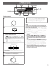
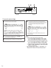
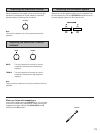
Operations ........................................ 13
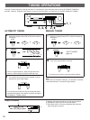
Tuning Operations ............................ 16
Using Digital Sound Field
Processor (DSP) ............................... 18
Setting the SLEEP Timer .................. 22
Remote Control Transmitter ............. 23
Notes about the Remote
Control Transmitter ........................... 26
Troubleshooting ................................ 27
Specifications ................................... 28
Block Diagram .................................. 29


