


3
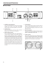
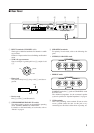
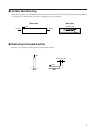
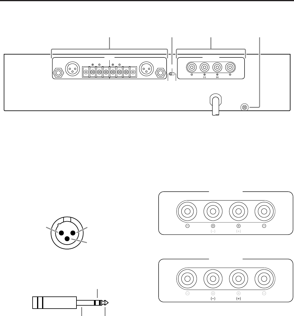
■ Rear Panel
INPUT SPEAKERS
CHANNEL B CHANNEL A
CHANNEL B CHANNEL A
GG
(BRIDGE)
(PARALLEL)
BRIDGE
STEREO PARALLEL
STEREO
BRIDGE
MAX. OUTPUT 450W/4Ω (STEREO)
MAX. OUTPUT 900W/8Ω (BRIDGE)
(STEREO)
4-8Ω/SP
(BRIDGE)
8-16Ω/SP
3214
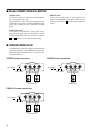
3 SPEAKERS terminals
For polarity in each mode, refer to the following dia-
gram.
• STEREO, PARALLEL mode
SPEAKERS
CHANNEL B CHANNEL A
STEREO
BRIDGE
• BRIDGE mode
SPEAKERS
CHANNEL B CHANNEL A
STEREO
BRIDGE
In BRIDGE mode, the (-) jacks of CHANNELS A and
B are not used.
The minimum impedance for the connected speaker
system is specified in “Speaker Impedance” on page 4.
4 GND terminals
This is the grounding screw terminal. If hum or noise
occurs, ground (earth) the unit via this jack, or try
connecting it to the chassis of the mixer or preamp, etc.
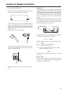
1 INPUT terminals (CHANNEL A, B)
Three types of balanced terminals for channels A and B
are provided.
Channel A input terminal is used in Bridge and Parallel
mode.
• XLR-3-31 type connector
They are wired pin 1–ground, pin 2–hot (
+
), and pin 3 cold
(
-
).
1
2
3
Cold
GroundHot
• Phone jack
They are wired tip–hot (+), ring–cold (-), and sleeve–
ground.
Ring
Sleeve Tip
• Barrier strip
Hot (+), Cold (-) and Ground (G).
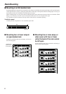
2 STEREO/BRIDGE/PARALLEL switch
This slide switch is used to set the amplifier operating
mode: STEREO, BRIDGE or PARALLEL.
For details on the functionality of each mode, refer to
“Modes” on page 4.