


4
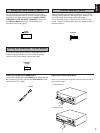
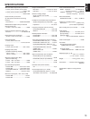
CONNECTIONS
●
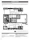
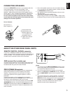
Before attempting to make any connections to or from this unit, be sure to first switch OFF the power to this unit and to any other
components to which connections are being made.
●
When making connections between this unit and other components, be sure all connections are made correctly, that is to say L
(left) to L, R (right) to R, “+” to “+” and “–” to “–”. Also, refer to the owner’s manual for each component to be connected to this
unit.
: Refer to “ABOUT THE OTHER REAR PANEL PARTS” on page 5.
A OR B:6
Ω
MIN./SPEAKER
A B:l2
Ω
MIN./SPEAKER
A
B
REMOTE
CONTROL
PHONO
GND
CD
TUNER
TAPE
PB
TAPE 1
REC
OUT
TAPE
PB
TAPE 2
REC
OUT
AUX
MAIN
IN
COUPLER
PRE
OUT
PHONO
AC OUTLETB
SWITCHED
200W MAX.TOTAL
MAINS
SPEAKERS
LINE OUT
LINE IN
OUTPUT
OUTPUT
AUDIO OUT
LINE OUT
LINE IN
OUTPUT
GND
Compact disc player
Turntable Video cassette player,
LD player, etc.
Tape deck 2 Speakers B
To AC outlet
(Europe model)
Right Left
Right Left
Tuner Tape deck 1 Speakers A
AC OUTLETS (SWITCHED)
(Europe and General models)
............................................................3 SWITCHED OUTLETS
(Australia model) ...................................1 SWITCHED OUTLET
Use these to connect the power cords from your components
to this unit.
The power to the SWITCHED outlets is controlled by this unit’s
POWER switch or the provided remote control transmitter’s
POWER key. These outlets will supply power to any
component whenever this unit is turned on.
The maximum power (total power consumption of
components) that can be connected to the SWITCHED AC
OUTLETS is 200 watts.