


6
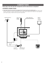
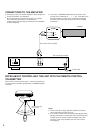
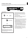
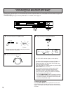
CONNECTIONS TO THE AMPLIFIER
●
Do not plug in this unit and the amplifier or other component
until all connections are completed.
●
Be sure that the connections from the left (“L”) and right
(“R”) LINE OUT terminals are connected to the
corresponding (left and right) input terminals of the amplifier
or other component.
●
If you have a YAMAHA amplifier whose terminals on the
rear panel are numbered as 1, 2, 3, etc., connections can
be made easily by making sure to connect the LINE OUT
terminals of this unit to the input terminals of the amplifier
numbered 2.
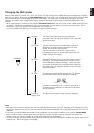
NOTES ABOUT CONTROLLING THIS UNIT WITH THE REMOTE CONTROL
TRANSMITTER
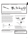
This unit has a remote control sensor. It receives signals from
a remote control transmitter provided with a YAMAHA amplifier
or receiver.
Notes
●
There should be no large obstacles between the remote
control transmitter and the main unit.
●
If the remote control sensor is directly illuminated by strong
lighting (especially an inverter type of fluorescent lamp etc.),
it might cause the remote control transmitter not to work
correctly. In this case, reposition the main unit to avoid
direct lighting.
75Ω UNBAL.
FM ANT GND AM ANT
LINE OUT
RL
2
TUNER
L
R
Amplifier
Connection cord (included)
This unit (Europe model)
To AC outlet
30°
30°
Remote control
sensor
Within approximately
6 m (19.7 feet)