


4
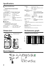
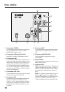
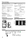
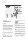
Rear Panel
A
POWER switch
This switch turns the power to the MS300 on and
off. When you turn this switch on, the POWER
indicator (
8
) lights up green.
B
AC IN connector
Connect the included power cord here.
C
LINE connectors
These balanced connectors accept input from
line-level sources, such as a mixer. The connec-
tors include: an XLR-3-31 type; an XLR-3-32
type; a 1/4" TRS phone jack. They are all con-
nected in parallel and can be used as line outputs.
In this case, input signals from the MIC connec-
tor (
5
) will not be output.
D
LINE LEVEL control
This control enables you to adjust the level of sig-
nal input from the LINE connectors (
3
).
E
MIC connector
Mic-level sources are input at this balanced,
XLR-3-31 type connector. The internal low-cut
filter will cut the range of these signals below
70 Hz. The mic input will not be routed to any
destination other than the speaker.
F
MIC control
This control enables you to adjust the level of sig-
nal input at the MIC connector (
5
).
G
MASTER LEVEL control
This control enables you to adjust the entire vol-
ume level.
H
POWER indicator
When you turn the power on, this indicator lights
up green.
I
EQ control
LOW:
This EQ adjusts the low band in the range
of 0 ~ –8 dB with a center frequency of 55 Hz.
The 0 (MAX) setting is flat. Turn the control
couterclockwise to cut.
HIGH:
This EQ adjusts the high band. The arrow
setting is flat. Turn the control clockwise to
boost and couterclockwise to cut the HF band
(1.6 kHz or higher) in the range of ±3 dB.
1
3
2
2
3
1
1
3
2
7
5
8
6
4
1
2
3
9