


IPA8200 Owner’s Manual
8
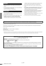
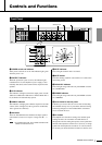
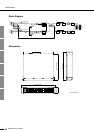
Controls and Functions
q
INPUT connectors
These are balanced input connectors. The included Eurob-
lock connectors can be used to make connections here.
w
SPEAKERS connectors
These are barrier strip type speaker output connectors.
• If using BRIDGE mode, connect the speakers to the “+”
pin of channels A/C/E/G and the “–” pin of channels B/
D/F/H.
• Do not connect the pin marked NC located in the center
of the bottom row of the barrier strip connectors.
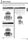
e
MODE switches
These specify the amplifier’s operation mode for each two
channels.
• STEREO mode
Each channel (A–H) will operate independently.
• BRIDGE mode
The amplifiers will be bridged for pairs of adjacent chan-
nels (A-B, C-D, E-F, G-H), obtaining a high-power out-
put.
•PARALLEL mode
The input signals will be input to the adjacent channels
(A-B, C-D, E-F, G-H) as well.
r
GAIN switch
This switches the input sensitivity / gain for all channels
together.
• +4 dBu:
Sets the input sensitivity to +4 dBu.
• 26 dB:
Sets the gain to 26 dB.
• 32 dB:
Sets the gain to 32 dB.
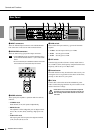
t
HPF switch
Turns the high pass filter (20 Hz or 55 Hz) on/off. If this is
set to 20 Hz or 55 Hz, the frequency components below that
frequency will be cut by a 12 dB/oct. filter.
y
Ground screw
Hum and interference may be reduced in some cases by con-
necting the screw to an ground or to the chassis of the mixer,
preamp, or other device in your system.
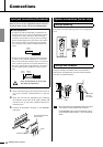
u
AC inlet
Connect this to the socket end of the included AC power
cable . Connect the plug end of the AC power cable to an AC
outlet of the correct voltage.
• If this device is to be rack mounted and transported
frequently, be sure to support the rear end of the unit
with mounting hardware that matches the size of the
rack used.
Rear Panel
t
uy
rwe
q
NOTE
CAUTION