


30 En
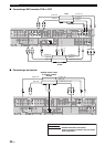
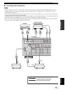
Connections
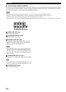
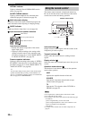
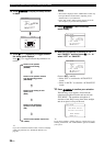
VIRTUAL indicator
Lights up when the Virtual CINEMA DSP mode is
active (see page 50).
SILENT CINEMA indicator
Lights up when headphones are connected and a
sound field program is selected (see page 50).
E
Multi-information display
Shows the name of the current sound field program and
other information when adjusting or changing settings.
F
SLEEP indicator
Lights up while the sleep timer is on (see page 46).
G
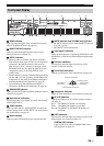
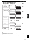
Input channel and speaker indicators
Input channel indicators
• Indicate the channel components of the current
digital input signal.
• Light up or flash according to the settings of the
speakers when this unit is in the automatic setup
procedure (see page 31) or in the “BASIC MENU”
in “MANUAL SETUP” (see page 70).
Presence speaker indicators
Light up or flash according to the setting of “EXTRA
SP ASSIGN” when this unit is in the automatic setup
procedure (see page 31) or in the “BASIC MENU” in
“MANUAL SETUP” (see page 68).
y
You can make settings for the presence and surround back
speakers automatically by running “AUTO SETUP” (see
page 31) or manually by adjusting settings for “SUR.B L/R
SP” (see page 69) in “SPEAKER SET”.
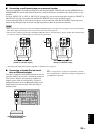
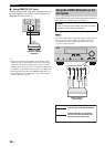
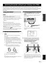
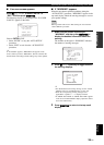
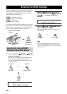
The remote control transmits a directional infrared ray.
Be sure to aim the remote control directly at the remote
control sensor on this unit during operation.
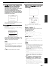
Infrared window (
1
)
Outputs infrared control signals. Aim this window at the
component you want to operate.
Transmit indicator (
2
)
Flashes while the remote control is sending infrared
signals.
Display window (
6
)
Shows the name of the selected input source that you can
control.
Operation mode selector (
F
)
The function of some buttons depends on the operation
mode selector position.
AMP
Operates the amplifier function of this unit.
SOURCE
Operates the component selected with an input
selector button (see page 84).
TV
Operates the TV assigned to either DTV/CBL or
PHONO (see page 83).
• Do not spill water or other liquids on the remote control.
• Do not drop the remote control.
• Do not leave or store the remote control in the following types
of conditions:
– places of high humidity, such as near a bath
– places of high temperatures, such as near a heater or stove
– places of extremely low temperatures
– dusty places
• To set the remote control codes for other components, see
page 85.
Input channel indicators
LFE
LL C R
SL SB SR
SBRSBL
LFE indicator
Presence speaker indicators
Using the remote control
Notes
30 30
Approximately 6 m
Remote control sensor