


4/10 (G/B)
High Current Amplification Achieves Low Impedance/
High Current Power from Input to Output.
The Importance of High Current
Although power rating is often the first
thing customers look at in a amplifier, high
power output does not necessarily mean
good sound. High current level is a much
more important factor. Yamaha amplifiers
has always had fairly high current levels,
but with the DSP-AX640SE, we have
further improved this performance.
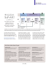
What It Does
In brief, Yamaha High Current
Amplification achieves low impedance,
high current power from input (power
supply circuit) to output (speaker
terminals). This drives the speakers much
more smoothly and dynamically, for better
sound from all sources, including 2-
channel audio.
Specific Improvements
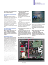
The first problem to be overcome was the
difference in voltage that ordinary
amplifiers suffer between the power
supply and amplifier circuits, caused by
current fluctuations. This was solved by
using custom-made, high-grade block
electrolytic capacitors and a copper grip
for one-point grounding. Another current
drop is generally seen between the
amplifier circuit and the speaker
terminals, caused by the cables, speaker
output relays, copper circuit boards, and
so on. To increase current here, we used
an extra-large, low-impedance
transformer and gold-plated speaker relay
contacts.
6-Channel High Power,
Discrete Amplifier Configuration
The DSP-AX640SE will deliver as much as
85W of power to each of six channels
(two main, two rear, one centre and one
rear centre). This is more than enough to
fill even the largest rooms with vibrant
music and Richter-scale sound effects. 6-
4 mixdown is also provided, for enjoying
6-channel input sources from four or five
speakers you already have on hand with
or without a subwoofer.
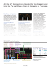
High Dynamic Power Capability
The DSP-AX640SE is capable of delivering
large amounts of reserve power for
accurate reproduction of the high energy
peaks that are especially prevalent in
digital audio sources. This emphasizes the
music’s dynamic qualities and provides a
sharper sound image.
Linear Damping (Main L/R Channels)
Level variations due to high amp
impedance tend to reduce an amplifier’s
damping factor, and frequency variations
cause it to fluctuate. This circuit cancels
the effect of these variations, maintaining a
high, stable damping factor, for superior
articulation of all sounds and better
frequency response.
Anti-Resonance ToP-ART Base
Supporting the heavy heat sinks and circuit
board is Yamaha’s ToP-ART base, which
has exceptional anti-resonance and
damping characteristics. Beneath this base
is the bottom of power amplifier, part of the
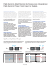
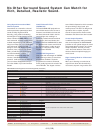
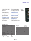
The voltage (A) of Block Electrolytic Capacitors and voltage (B) of
Power Transistor Collector should be ideally at the same level. However,
when the current become large, there will be a big difference in the
level of each voltages.
Voltage level difference between A (power supply circuit) and B
(amplifier circuit).
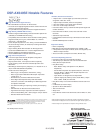
Voltage level difference between C (amplifier circuit output) and D
(speaker terminals).
High Current Amplification
Conventional Amplifier
High Current Amplification
Conventional Amplifier
There is also a level difference between Output of the Power Amplifier
(C) and Speaker Terminals (D), which is caused by the copper of the PCB,
Speaker output relays, cables and so on, resulting in reduced sound
quality.
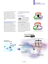
GND
Power
Supply
Circuit
Amplifier
Circuit
A
B
GND
Power
Supply
Circuit
Amplifier
Circuit
C
D
High Current Amplification Principle