


13
EnglishBASIC OPERATION
ADVANCED OPERA
TION APPENDIX
INTRODUCTION
PREPARATION
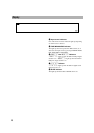
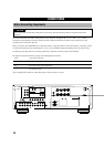
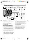
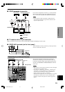
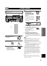
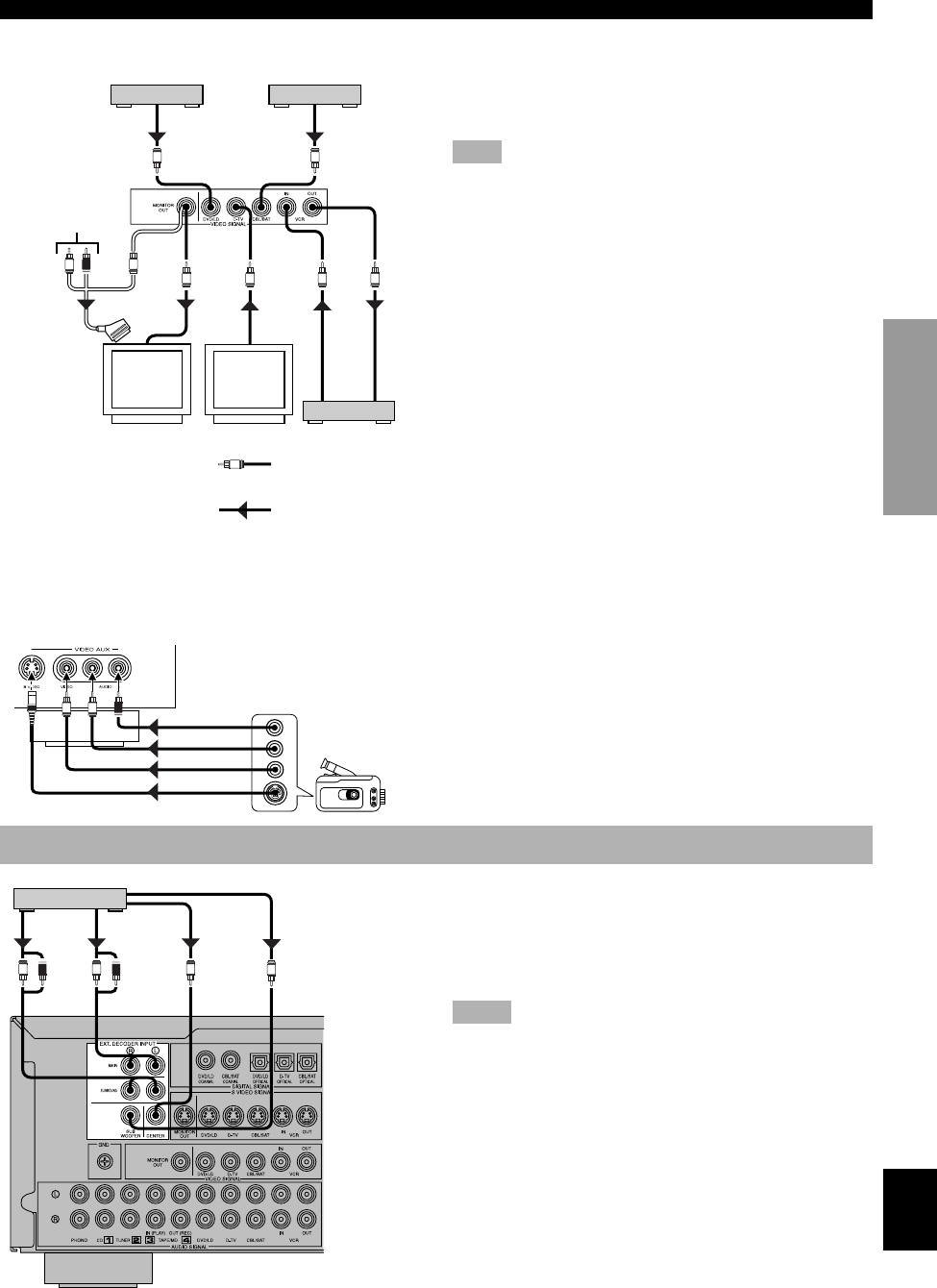
■ VIDEO terminals (composite)
If your video components do not have “S” video terminals,
they can be connected to this unit’s VIDEO terminals. Be
sure to connect the input (IN) and output (OUT) properly.
Note
• If video signals are input from both the S VIDEO input and
composite input terminals, the signals will be directed to their
respective output terminals.
■ TV monitor with a 21-pin connector
Make a connection as shown above with a commercially available SCART-plug connector cable.
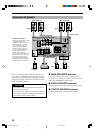
■ VIDEO AUX terminals (on the front panel)
These terminals are used to connect any video input source
such as a camcorder to this unit.
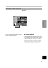
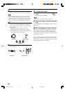
Connecting to an External Decoder
This unit has additional 6-channel audio signal input
terminals for connecting an external decoder to this unit.
Connect the 6-channel audio signal output terminals of the
decoder to the EXTERNAL DECODER INPUT terminals
of this unit.
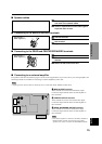
Notes
• When a source connected to these terminals is selected, the digital
sound field processor cannot be used.
• The settings of “CENTER SP”, “REAR SP”, “MAIN SP” and
“BASS OUT” on the SET MENU have no effect on a source
connected to these terminals. The setting of “MAIN LVL” is
effective. (Refer to pages 30 and 31 for details.)
• Adjustment of the output level of the center speaker, rear speakers
and subwoofer is effective when a source connected to these
terminals is selected as the input source. (Refer to page 33 for
details.)
CONNECTIONS
L R
V
AUDIO OUT R
AUDIO OUT L
VIDEO OUT
S VIDEO OUT
S
DVD/LD player
L R L R
MAIN
OUT
SURROUND
OUT
CENTER
OUT
SUBWOOFER
OUT
External decoder
(Europe model)
V
V
VIDEO
IN
V
L R
V
VIDEO OUT
V
VIDEO OUT
V
VIDEO
OUT
V
VIDEO
OUT
V
VIDEO
IN
Cable TV/satellite tuner
TV/digital TV
VCR
SCART-plug
No
connection
Video signal
Signal flow
Camcorder
TV monitor
0103DSP-A509-18_EN 2/29/0, 4:53 PM13