


DS60-112
7
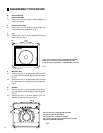
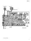
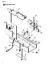
B. Amplifier Unit
6. MAIN circuit board 1/4
6-1. Remove the amplifier unit (See Item 4 above.)
6-2. Remove the four (4) screws marked [30], four (4) knobs
of Rotary variable resisters, four (4) hexagonal nuts
and one (1) each of INPUT and SLAVE OUT hexagonal
nuts. The MAIN circuit board 1/4 can then be removed.
(Fig. 3)
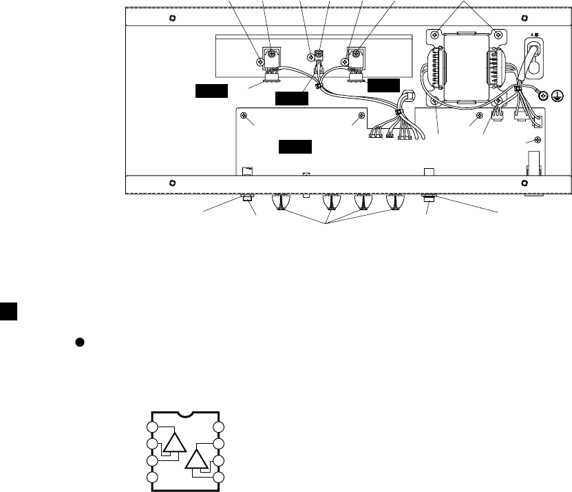
7. MAIN Circuit Boards 2/4, 3/4, 4/4
7-1. Remove the amplifier unit. (See Item 4 above.)
7-2. Remove the one (1) screw marked [210] from each
circuit board, which can then be removed. (Fig. 3)
8. Power Transformer
8-1. Remove the amplifier unit. (See Item 4 above.)
8-2. Remove the four (4) screws marked [190A]. The
power transformer can then be removed. (Fig. 3)
9. Heat Sink
9-1. Remove the amplifier unit. (See Item 4 above.)
9-2. Remove MAIN circuit boards 2/4, 3/4 and 4/4.
(See Item 7 above)
9-3. Remove the three (3) screws marked [190B]. The
heat sink can then be removed. (Fig. 3)
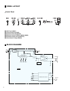
Fig.3
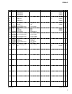
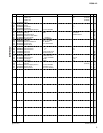
[30]: Bind Head Tapping Screw-B 3.0X8 MFZN2BL (EP600190)
[190]: Bind Head Tapping Screw-C 4.0X8 MFZN2BL (VC688900)
[210]: Bind Head Screw SP3.0X12 MFZN2Y (VB763800)
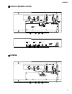
IC BLOCK DIAGRAM
RC4558D-V (IG001390)
IC1, IC2
OP AMP
1
2
3
4-V
+V
8
7
6
5
Output A
Non-Inverting
Input A
-DC Voltage Supply
+DC Voltage
Supply
Output B
Inverting
Input B
Non-Inverting
Input B
Inverting
Input A
+-
+-
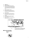
[190B]
[30] [30]
[30]
[190A] [190A]
[30]
[190B] [190B] [190A][210] [210][210]
Hexagonal nut
INPUT
SLAVE OUT
Knob
Hexagonal nut
1/4MAIN
2/4MAIN
3/4MAIN
4/4MAIN