


7
English
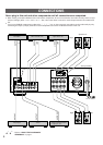
Connect the SPEAKERS terminals to your speakers with wire
of the proper gauge, cut as short as possible. If the
connections are faulty, no sound will be heard from the
speakers. Make sure that the polarity of the speaker wires is
correct, that is, + and – markings are observed. If these wires
are reversed, the sound will be unnatural and lack bass. Do
not let the bare speaker wires touch each other or the
metal parts of this unit as this could damage this unit
and/or speakers.
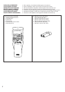
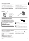
How to Connect:
Red: positive (+)
Black: negative (–)
➀
Unscrew the knob.
➁
Insert the bare wire.
[Remove approx. 5mm
(1/4”) insulation from
the speaker wires.]
➂
Tighten the knob and
secure the wire.
●
One or two speaker systems can be connected to this unit.
If you connect only one speaker system, connect it to either
the SPEAKERS A or B terminals.
●
Use speakers with the specified impedance shown on the
rear of this unit.
● <China and General models only>
Banana Plug connections are also possible. Simply insert
the Banana Plug connector into the corresponding terminal.
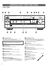
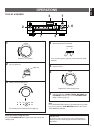
CONNECTING SPEAKERS
ABOUT THE ACCESSORY TERMINALS
AC OUTLET(S) (SWITCHED)
(Europe, China and General models)
.......................................................... 3 SWITCHED OUTLETS
(U.K. model) ........................................ 1 SWITCHED OUTLET
Use these to connect the power cords from your components
to this unit.
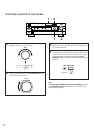
The power to the SWITCHED outlets is controlled by this unit’s
STANDBY/ON switch or the provided remote control
transmitter’s POWER key. These outlets will supply power to
any component whenever this unit is turned on.
The maximum power (total power consumption of components)
that can be connected to the SWITCHED AC OUTLET(S) is
100 watts.
GND terminal (For turntable use)
Connecting the ground wire of the turntable to this terminal will
normally minimize hum, but in some cases better results may
be obtained with the ground wire disconnected.
1
2
3
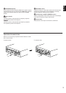
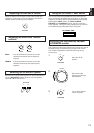
Be sure to switch this only when the power to this unit is not
on.
Select the position whose requirements your speaker system
meets.
WARNING
Do not change the IMPEDANCE SELECTOR switch
setting while the power to this unit is on, otherwise this
unit may be damaged.
IF THIS UNIT FAILS TO TURN ON WHEN THE
STANDBY/ON SWITCH IS PRESSED;
The IMPEDANCE SELECTOR switch may not be set to
either end closely. If so, set the switch to either end closely.
(Upper position)
If you use one pair of speakers, the impedance of each
speaker must be 4Ω or higher.
If you use two pairs of speakers, the impedance of each
speaker must be 8Ω or higher.
(Lower position)
If you use one pair of speakers, the impedance of each
speaker must be 6Ω or higher.
If you use two pairs of speakers, the impedance of each
speaker must be 12Ω or higher.
IMPEDANCE SELECTOR switch
A OR B : 4
Ω
MIN. /SPEAKER
A B : 8
Ω
MIN. /SPEAKER
A OR B : 8
Ω
MIN. /SPEAKER
A B : 12
Ω
MIN. /SPEAKER
IMPEDANCE SELECTOR
SET BEFORE POWER ON
*
1
*
2