


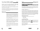

Input Sensitivity Adjustment
The X%(" offers five ()) input gain settings* The adjustment runs in $( dB steps
from +!( dB to . !( dB* This wide range of adjustment allows the X%(" to accept
input voltages from $(( mV to $# V* Adjustment is made by installing a jumper
across the associated input voltage/pin location* Refer to the illustration on the
reverse side of this document prior to setting the input sensitivity*
Crossover Frequencies & SIP’s
The X%(" is equipped with independent Front and Rear crossovers* Each
crossover is controlled by two (!) crossover mode jumpers labeled
AAMMP & LINE
XXOVRR
*
The header jumper labeled
AAMMP XXOVRR
control the crossover function as
it applies to the X%("’s Front (stereo) and Rear (stereo) amplifier* The modes of
operation are: Position $ / Bypass (Full Range), Position ! / High Pass, and
Position ' / Low Pass and Position "/Band Pass (See insert)
The two (!) header jumpers labeled
LINE XXOVRR
control the crossover function
as it applies to the X%("’s Front and Rear RCA Line Outputs* The modes of oper+
ation are: Position $ / Bypass (Full Range), Position ! / High Pass, and Position
' / Low Pass* (See insert)
The High and Low Pass frequencies are determined by the Frequency Modules (SIPs)
installed in the eight (-) SIP sockets pictured on the insert*
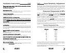
Crossover Frequencies & SIP’s
The following is a chart of Xtant’s available frequencies* The frequency SIP “ID
Code” printed on the SIP and the associated frequency value is detailed below*
SIP Number Frequency
!!" )( Hz
$'" #( Hz
$$" -( Hz
$(" &( Hz
%-' $!( Hz
)%' $)( Hz
!#' '(( Hz
$)' )(( Hz
$(' #(( Hz
#)! $ kHz
!"! ' kHz
$-! " kHz
$)! ) kHz
The X%(" is shipped from the factory with &( Hz HiPass and LowPass frequency
SIP’s installed* To change a frequency, simply remove the resistor SIP and replace it
with the appropriate SIP value to achieve the desired frequency*
The Low and High Pass frequencies are independent* Any combination of the available
frequency SIP’s may be used*
4 5
Installation Instructions
This document has been crafted to make installation, system design and trouble+
shooting, a quick and easy process*
Installation Sequence
Remove Amplifier Cover:
Loosen allen head screws and lift+off cover* Do not remove protective
covering on stainless steel lid until installation is complete*
Temporarily Mount Amplifier:
The amplifier is designed to be anchored through the four (") holes located on the
circuit board/base assembly*
Mark Wires for Termination and Remove X%(":
Determine wire lengths for Power, Ground, Remote, & speaker cables* Mark for
cutting/termination* Remove X%(" before cutting and terminating all wires*
CAUTION:
stripping wires over the circuit board will cause product failure*
Crossover Set+up:
Adjust crossover mode jumpers at your work bench* Also, change crossover frequency
SIP’s if desired* Refer to crossover modes of operation on opposite page*
Input Sensitivity:
Make initial adjustment to input gain at your work bench* To increase input gain,
place jumper in the .!( dB position* To decrease input gain, place jumper in the
(, +$(, or +!( dB position* Refer to Input Sensitivity Adjustment on back panel for
more information*
Mount the Amplifier and make all connections:
NOTE:
Place service jumper in off position before making any connections* Install
the amplifier and make all wire connections* i*e:*Speaker, Power, Remote,
Ground, and RCA input*
Double Check All Connections! Turn On Amplifier*
Place service jumper in the on position, check red LED, it should be on*
Adjust Left and Right Front as well as Left and Right Rear Amplifier Output Levels*
Adjust Noise Gate Threshold (if used)
Turn noise gate on and adjust the threshold by turning clockwise to increase
sensitivity* The green LED will illuminate*
After Fine Tuning the System:
Remove protective covering from amplifier and clean per the maintanence section
on page & of the
Owner’s Manual*
Attach cover to base*
English English