


4 5
Installation Instructions
This document has been crafted to make installation* system design and
trouble+shooting* a quick and easy process,
Installation Sequence
Remove Amplifier Cover:
Loosen allen head screws and lift+off cover, Do not remove protective covering
on stainless steel lid until installation is complete,
Temporarily Mount Amplifier:
The amplifier is designed to be anchored through the four (") holes located on
the circuit board/base assembly,
Mark Wires for Termination and Remove X$(($:
Determine wire lengths for Power* Ground* Remote* & speaker cables, Mark for
cutting/termination, Remove x$(($ before cutting and terminating all wires,
CAUTION: stripping wires over the circuit board may cause product failure,
Crossover Set+up:
Adjust crossover mode jumpers at your work bench, Also* change crossover
frequency SIP’s if desired, Refer to crossover modes of operation on opposite page,
Input Sensitivity:
Make initial adjustment to input gain at your work bench, To increase input gain*
place jumper in the -!( dB position, To decrease input gain* place jumper in the
(* +$(* or +!( dB position, Refer to Input Sensitivity Adjustment on back panel for
more information,
Mount the Amplifier and make all connections:
Install the amplifier and make all wire connections, i,e: Speaker* Power* Remote*
Ground* and RCA input,
Double Check All Connections! Turn On Amplifier,
Check red LED* it should be on,
Adjust Amplifier Output Gain Pot,
After Fine Tuning the System:
Remove protective covering from amplifier and clean per the mainta+
nence section on page & of the
Owner’s Manual,
Attach cover to base,
English
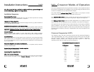
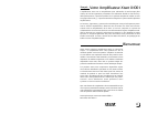
Crossover Modes of Operation
The $(($x is equipped with a two+way electronic crossover, The Lowpass function of
the crossover is dedicated to the amplifier (x$(($) and the High pass function of the
crossover is available at the on+board RCA line outputs,
The jumper labeled
Lowwpass SSlopee SSeeleect
allows either $! or !" dB per octaves
slopes to be selected for the Lowpass function of the x$(($,
The
Liinee Out MModdee SSeeleect
jumper controls the function of the on+board RCA
line outputs and offers two (!) modes of operation: Bypass and high pass,
The
Hiigh pass SSlopee SSeeleect
jumper provides independent $! or !" dB per octave
slope selection for the High pass function available at the RCA Line Outputs,
The High and Low Pass frequencies are determined by the Frequency Modules
(SIPs) installed in the three (') SIP sockets pictured on the insert, One SIP
determines the Lowpass frequency* while two (!) SIPs determine the High pass
frequency, Each frequency setting is independent and may be changed to suit
your needs,
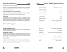
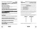
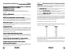
Crossover Frequencies & SIP’s
The frequency (SIP) “ID Code” printed on the SIP and the associated frequency
value is detailed below, The x$(($ is shipped from the factory with &( Hz high
pass and LowPass frequency modules (SIP) installed, To change a frequency
module* simply remove the resistor SIP and replace it with the
appropriate SIP value to achieve the desired frequency,
CROSSOVER FREQUENCIES & SIP’S
SIP Number Frequency
!!" )( Hz
$'" #( Hz
$$" .( Hz
$(" &( Hz
%.' $!( Hz
)%' $)( Hz
!#' '(( Hz
$)' )(( Hz
$(' #(( Hz
#)! $ kHz
!"! ' kHz
$.! " kHz
$)! ) kHz
English