


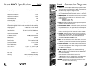
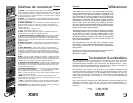
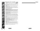

Connection Diagrams
1. Input – Xtant A series amplifiers feature RCA type input connections.
Source units with an output signal level of 100mV – 17V may be used.
See "Balanced Input" for proper voltage level setting.
2. Output – These RCA type output connections send full range sig-
nals to additional amplifiers eliminating the need for "Y" connectors.
3. Balanced Input – The balanced input switch serves two purposes.
First, it helps eliminate noises being induced into the signal path by
isolating the signal ground. Second, it is used to set the proper
input voltage range:
Off Position: 100mV – 8V
On Position: 200mV – 17V
4. Gain – This feature is used to fine-tune the input sensitivity of the
amplifier to the source unit’s output level.
5. Xover Frequency Control – This control allows the user to choose
the exact low-pass frequency range the amplifier will play for the
best possible performance. The upper end of the crossover frequen-
cies can be selected from 40Hz – 120Hz at 24dB per octave.
6. Bass Boost – This feature will add up to 12dB of low frequency
impact to the audio system. The Bass Boost is centered at 45Hz.
7. Subsonic – This feature limits the lower end of the low-pass fre-
quencies sent to the subwoofers. The subsonic feature includes a
selectable on/off switch, and a control knob used to adjust the
lower end of the low-pass range. The subsonic setting can be
selected from 20Hz-80Hz at 24dB per octave.
8. RLC – This port allows the use of the optional Xtant "remote level
control" (RLC). The RLC is a bass control module that can be
installed in any location within the vehicle for remote adjustments.
9. Speaker Connection – Two sets of speaker terminals are provid-
ed for dual woofer applications. When connecting a single woofer,
use only one set of speaker terminals. Warning, the Xtant A3001
and A6001 are not bridgeable.
10. Power Terminals – This is the main power connection for the
amplifier. The power and ground wire size should be the same gauge.
GND – The ground wire from this connection must be attached to
bare metal on the vehicle.
REM – To turn the amplifier on/off, this terminal must be connected
to the source unit’s "remote or electric antenna" wire.
+12V – The power wire from this connection must be attached to
an inline fuse, then to the positive side of the vehicle battery.
WARNING: An outboard fuse must be installed in-line with the power
wire within 18 inches of the battery.
9
10
1
2
3
4
5
6
7
8
English
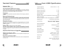
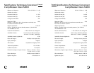
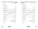
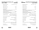
Xtant A6001 Specifications
Frequency Response: 20 Hz to 120 Hz +/– 1 dB
Number of Channels: 1
Watts per Channel @ 4Ω: 1 x 300
Watts per Channel @ 2Ω: 1 x 600
Recommended Load: ≥2Ω
Distortion (THD): ≤ 2%
Measured: 20 Hz to 120 Hz at rated power, all channels driven 4Ω
Signal to Noise Ratio: ≥ 100 dB
Measured: A-weighted in 20 kHz noise bandwidth @ 1 volt sensitivity
Damping Factor: ≥ 100 @ 100 Hz with 4Ω load
Input Sensitivity: 100 mV to 8.5 V RMS Unbalanced
200 mV to 17 V RMS Balanced
Input to Line Output Gain: 0 dB
On-Board Crossover: 24 dB/Octave Low Pass
Balanced Line: On Board
Power Supply: Fully Regulated, PWM
Operational Voltage: 10 to 16 Volts
Fusing Requirement: 80 Amp
Size (L xW x H): 15-13/16” x 9-1/4” x 1-7/8”
402mm x 235mm x 47mm
Subsonic Filter: 24dB/Octave 20-80 Hz
Bass Boost: 0-12dB @ 45 Hz
Warranty: Limited 4 Year Parts and Labor
(see page 8 for details)
English
6 7