


3
Amplifiers & Preamplifiers
PA640 PANEL DESCRIPTIONS
SYLMAR, CA MADE IN U.S.A.
POWER
REMOTE
ON/OFF
CH1 CH2
BRIDGED
STEREO
LEVEL
LEVEL
LINE INPUTS
LINE INPUTS
BRIDGED
STEREO
CH3 CH4
LEVEL
CH5 CH6
LINE INPUTS
BRIDGED
STEREO
1
2
3 4 5
3 4 5 3 4 5
PA640
SIX CHANNEL POWER AMPLIFIER
®
1V
.2V3V
1V
.2V3V
1V
.2V3V
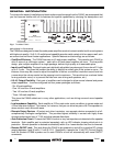
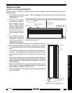
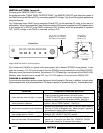
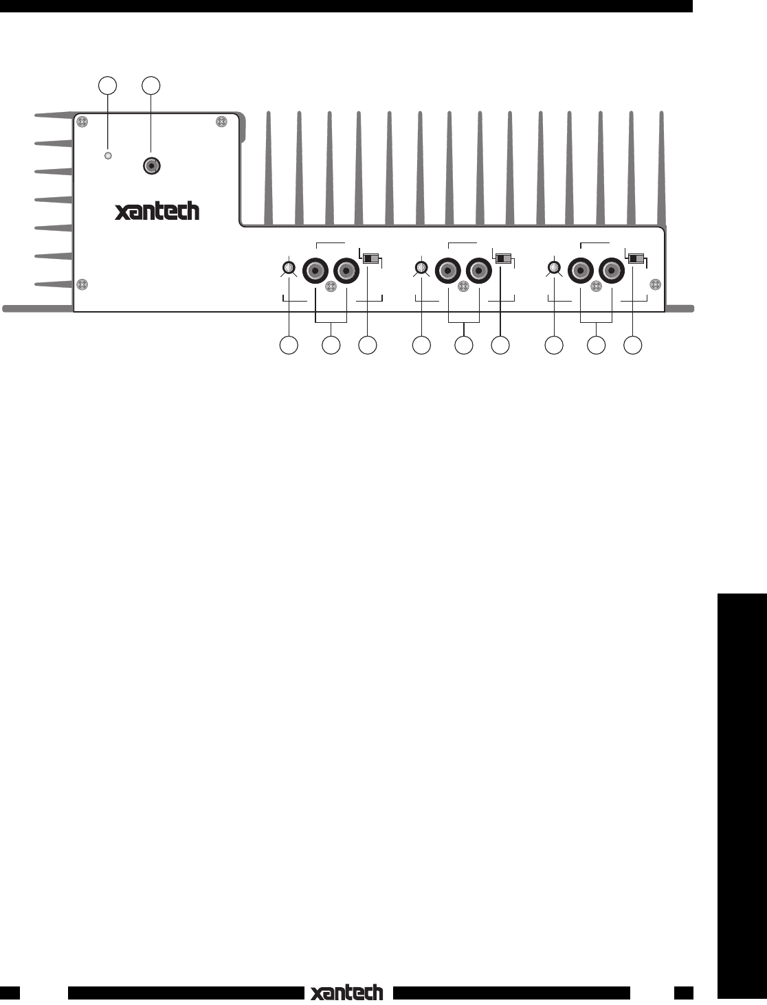
Fig. 2 PA640 Input Panel –
Features and Functions
1. POWER Indicator LED. This green LED lights when power is turned on by the POWER switch (item
# 8) or by a DC voltage applied to the REMOTE ON/OFF jack (item #2).
2. REMOTE ON/OFF Jack. This 3.5mm mono mini jack allows the PA640 to be powered on and off by
a positive DC voltage ranging between 4 and 30 volts (11 mA @ 12 V). For instance, it permits the
12 Volt CO (Control Output) from a Xantech ZPR68 IR controlled preamp to power the PA640 ON and
OFF automatically with zone ON/OFF commands. The DC Voltage must be applied continuously to
hold the ON condition and go to less than 0.5 Volt for the OFF condition.
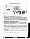
NOTE:
The POWER switch (item #8) must be left in the MANUAL OFF (REMOTE ON/OFF)
position to permit the REMOTE ON/OFF jack to operate.
3. Input LEVEL Control. This screwdriver adjustable control (for each stereo or bridged pair) allows the
input level for full rated power output to be adjusted over a range of 0.2 volts to 3.3 volts (24.3 dB).
Normally you would adjust the driving preamp to max. volume, then set this control to the maximum
volume that the client desires for a given zone or room. This prevents the system from being driven
to potentially destructive power levels.
4. LINE INPUTS. These RCA type jacks are the audio inputs for the amplifier. Connect them to the
OUTPUT jacks of the driving preamp with good quality RCA type patch cables. Note that the inputs
are marked CH1, CH2, CH3, etc., signifying the individual channels. They correspond to the like
marked speaker terminals on the OUTPUT & AC panel (item # 7). When the switches (item #5) are
set to the BRIDGED mode, CH1, CH3 and CH5 become the active inputs and CH2, CH4 and CH6
are disabled.
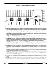
5. BRIDGED/STEREO Switches. These switches allow each of the three pair of amplifiers to be placed
in either the BRIDGED 140 Watt (single channel) mode, or in the STEREO 40 Watts/channel (two
channel) mode.
CAUTION: Be sure to have the POWER turned OFF when changing the position of this switch and
when making the corresponding speaker connection changes.
PA640