


Model PA1235X Page 5
© 2002 Xantech Corporation.
--
0
LEFT RIGHT
1
LEFT RIGHT
2
LEFT RIGHT
33
LEFT RIGHT
4
LEFT RIGHT
5
LEFT RIGHT
6
1V
.2V3V
LEVEL
1V
.2V3V
LEVEL
1V
.2V3V
LEVEL
1V
.2V3V
LEVEL
1V
.2V3V
LEVEL
1V
.2V3V
LEVEL
GROUND
LEFT RIGHT
SPEAKER
+-- --+
+ BRIDGED --
LEFT RIGHT
SPEAKER
+-- --+
+ BRIDGED --
LEFT RIGHT
SPEAKER
+-- --+
+ BRIDGED --
LEFT RIGHT
SPEAKER
+-- --+
+ BRIDGED --
LEFT RIGHT
SPEAKER
+-- --+
+ BRIDGED --
LEFT RIGHT
SPEAKER
+-- --+
+ BRIDGED --
REMOTE MASTER
ON/OFF CONTROL
5-30 VOLTS DC
+--
AC LINE
ON/OFF
STEREO
MONO
BRIDGED
MODE
STEREO
MONO
BRIDGED
MODE
STEREO
MONO
BRIDGED
MODE
STEREO
MONO
BRIDGED
MODE
STEREO
MONO
BRIDGED
MODE
STEREO
MONO
BRIDGED
MODE
WARNING
: TO REDUCE
THE RISK OF FIRE OR
ELECTRICAL SHOCK, DO
NOT EXPOSE THIS UNIT TO
RAIN, MOISTURE OR PLACE
WATER FILLED OBJECTS ON
THE PRODUCT.
ATTENTION
: RISQUE DE
CHOC ELECTRIQUE
NE PAS OUVRIR.
NO USER SERVICABLE
PARTS INSIDE.
CAUTION
NEUTRAL
FUSING
ATTENTION
:
POUR UN REGLAGE
CORRECT, SE
REPORTER AU
MANUEL
DINSTRUCTIONS.
WARNING
TURN POWER
OFF BEFORE
CHANGING
MODES
WARNING
TURN POWER
OFF BEFORE
CHANGING
MODES
REFER TO OWNERS
MANUAL FOR SAFETY
INSTRUCTIONS.
THIS DEVICE COMPLIES
WITH PART 15 OF THE
FCC RULES.
OPERATION IS SUBJECT
TO THE FOLLOWING
TWO CONDITIONS: (1)
THIS DEVICE MAY NOT
CAUSE HARMFUL
INTERFERENCE, AND (2)
THIS DEVICE MUST
ACCEPT ANY
INTERFERENCE
RECEIVED,
INCLUDING
INTERFERENCE THAT
MAY CAUSE UNDESIRED
OPERATION.
FUSE
10 AMP
SLOW BLOW
AC 120V
60Hz 8.7A
1044 WATTS
MODEL PA1235X
5
7 7
5
7
8
55
7
5
7
5
7
6
10
11
12
13
14
9
6
9
6
9
6
9
6
9
6
9
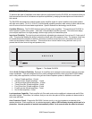
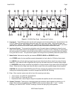
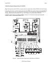
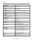
Figure 3 – PA1235X Rear Panel – Features and Functions
5. Line Inputs. These RCA-type jacks are the audio inputs for each of the amplifier pairs. Connect them to the
OUTPUT jacks of the driving preamp with good quality RCA-type patch cables. Note that the inputs are
marked LEFT-1-RIGHT, LEFT-2-RIGHT, etc., signifying the stereo channel pairs. Both the LEFT and RIGHT
jacks are also active when the MODE switch (item #7) is set to the MONO or BRIDGED mode.
6. Input Level Control. This screwdriver adjustable control (for each stereo or bridged pair) allows the input
level for full rated power output to be adjusted over a range of 0.2 volts to 3 volts. Normally you would adjust
the driving preamp to maximum volume, then set this control to the maximum volume that the client desires
for a given zone or room. This prevents the system from being driven to potentially destructive power levels.
7. Mode Switch. Switches the amplifier pair between STEREO, MONO and BRIDGED modes.
a) In STEREO mode, the two amplifiers operate independently of each other for 35 Watts of output each.
b) In MONO mode, left and right input signals are summed internally for Mono output from each of the two
amplifiers. Also, either the Left or Right (item #5) input may be used if the source is already a Mono signal.
c) In BRIDGED mode, the two amplifiers are bridged for a single channel of high power output (80 Watts @ 8
Ohms). Either the Left or Right input (item #5) may be used to drive the resultant single channel amplifier.
CAUTION: Be sure to have the POWER turned OFF when changing the position of this switch and when
making the corresponding speaker connection changes (see also item #9, following).
8. Fuse. When required, replace only with a fuse of the same type and rating:
x 120 V Version: 10 A 250 VAC, SLOW BLOW.
x 240 V Version: 5 A Time-Lag 250 VAC.
x Replacement with a fuse of higher rating will not protect the amplifier and will void the warranty.
9. Speaker Terminals. These plug-in 4-terminal screw type connectors permit speaker wire sizes up to 12-
gauge. When making connections for the STEREO mode, be sure to observe the "+” and "–" polarity
markings, just under the LEFT & RIGHT markings, for each wire pair going to the speakers.