


4
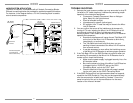
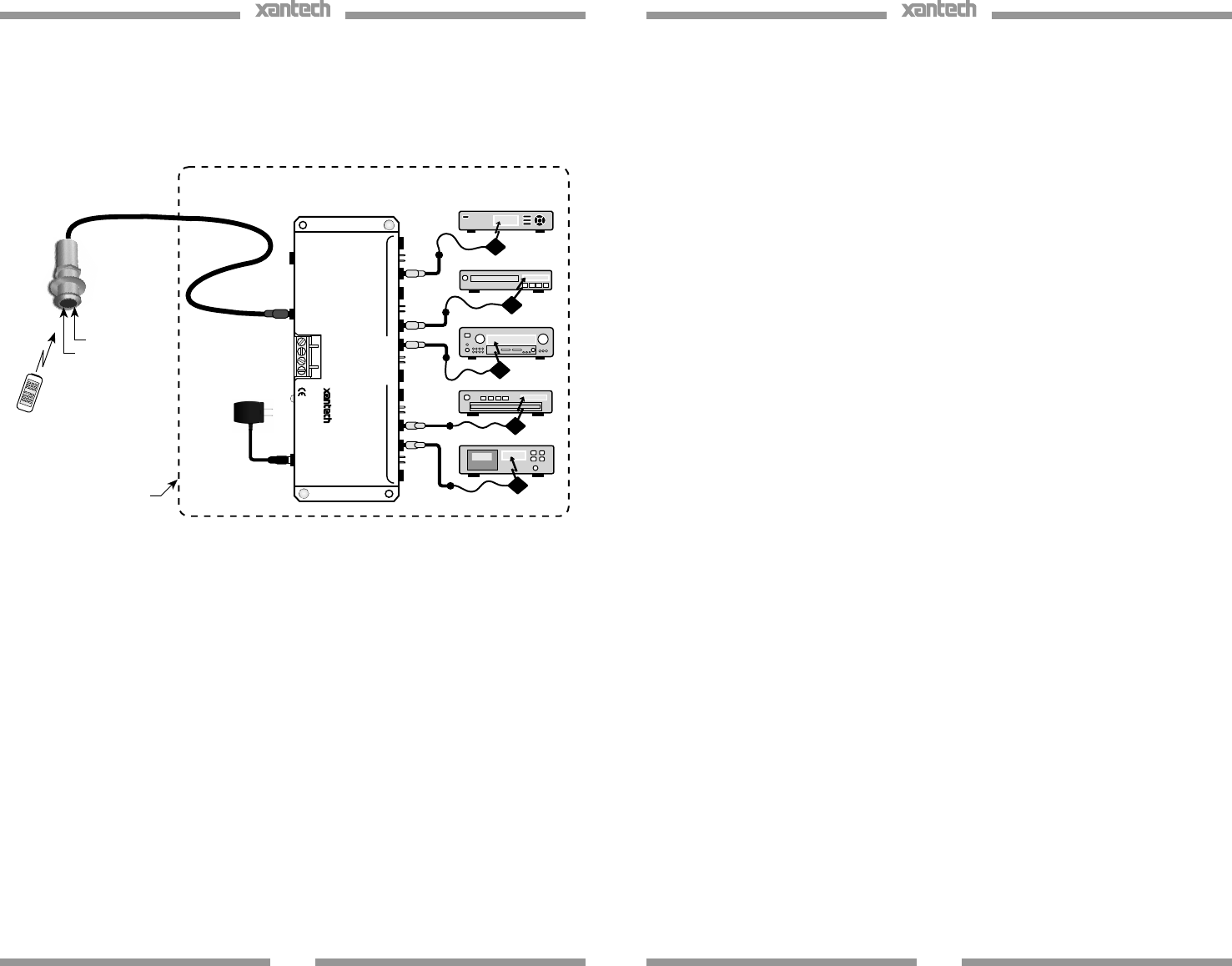
LARGE SYSTEM APPLICATION
The ML85 IR receiver is compatible with all Xantech Connecting Blocks.
Different connecting blocks are provided for application specific situations.
For instance, in the diagram below, a 791-44 connecting block is used to
control several components.
To 120 VAC
(unswitched)
Emitter
Emitter
Controlled Equipment
(mounted behind
closed cabinet doors)
Emitter
Emitter
Satellite Receiver
VCR
AVReceiver
CD Changer
Cassette Deck
ML Series
IR Receivers
Hand Held
Remote
IR Photodiode
Talkback LED
791-44
Amplified
Connecting Block
+12VDC
GND
EMITTERS
12VDC
HIGH
IR
OUT
STATUS
IR IN
IR
RCVR
791- 44
AMPLIFIE D
CONNECTING BLOCK
®
781ERGPS
Emitter
5
TROUBLE SHOOTING:
1. Perhaps the most common problem you may encounter is stray IR
(infrared) or RF (radio frequency) interference preventing proper
operation of the controlled equipment.
• Fluorescent, Compact Fluorescent, Neon or Halogen
lights, Neon Art, and light dimmers.
• Direct of reflected sunlight.
• Infrared security sensors (active types).
• RF radiation from TV sets that may be close to the Micro
Link IR Receiver.
2. You can confirm the source of the interference by temporarily
turning off TV sets, isolating the Micro Link IR Receiver from all
sunlight and turning off all lights, light dimmers and Infrared
security systems. Then check to see if the Micro Link IR Receiver
operates the component.
• Sometimes interference will cause the red Talk-Back LED
on the front of the Micro Link IR Receiver to blink dimly,
intermittently, or continuously.
• The Talk-Back Led should only blink when you are
sending infrared commands to the Micro Link IR receiver
from a remote control.
• It may be necessary to move either the interfering source
of the Micro Link IR Receiver to achieve proper operation.
3. If the Talk-Back LED or the 286D Emitters do not blink when you
are sending IR commands to the Micro Link IR Receiver from a
remote control, check the following:
• Make sure the power supply is plugged securely into a live
AC electrical outlet.
• Be sure the stereo mini plug of the Micro Link IR Receiver
is plugged into the “IR RCVR” jack on the CB12
Connecting Block, not into the “OUT” jack.
• Check to see that all the mini plugs are properly seated
into the mini jacks on the CB12 Connecting Block.
4. If the 283D Emitters blink, but the component does not respond,
reposition the 283D Emitter(s). They may not be located directly
over the component’s infrared receiving “window”. Consul the
owner’s manual of the unit or the manufacturer for the exact
location of the infrared “window”.