


Page 15Page 14
ANTENNA CONSIDERATIONS
The choice of antennas is a critical
and often overlooked design
consideration. The range,
performance, and legality of an RF link
are critically dependent upon the
antenna. While adequate antenna
performance can often be obtained by
trial and error methods, antenna
design and matching is a complex
task. A professionally designed
antenna, such as those from Linx, will
help ensure maximum performance and FCC compliance.
Linx transmitter modules typically have an output power that is slightly higher
than the legal limits. This allows the designer to use an inefficient antenna, such
as a loop trace or helical, to meet size, cost, or cosmetic requirements and still
achieve full legal output power for maximum range. If an efficient antenna is
used, then some attenuation of the output power will likely be needed. This can
easily be accomplished by using the LADJ line or a T-pad attenuator. For more
details on T-pad attenuator design, please see Application Note AN-00150.
A receiver antenna should be optimized for the frequency or band in which the
receiver operates and to minimize the reception of off-frequency signals. The
efficiency of the receiver’s antenna is critical to maximizing range performance.
Unlike the transmitter antenna, where legal operation may mandate attenuation
or a reduction in antenna efficiency, the receiver’s antenna should be optimized
as much as is practical.
It is usually best to utilize a basic quarter-wave whip until your prototype product
is operating satisfactorily. Other antennas can then be evaluated based on the
cost, size, and cosmetic requirements of the product. You may wish to review
Application Note AN-00500 “Antennas: Design, Application, Performance”
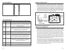
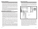
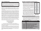
ANTENNA SHARING
In cases where a transmitter and receiver
module are combined to form a transceiver,
it is often advantageous to share a single
antenna. To accomplish this, an antenna
switch must be used to provide isolation
between the modules so that the full
transmitter output power is not put on the
sensitive front end of the receiver. There
are a wide variety of antenna switches that
are cost-effective and easy to use. Among
the most popular are switches from Macom and NEC. Look for an antenna
switch that has high isolation and low loss at the desired frequency of operation.
Generally, the Tx or Rx status of a switch will be controlled by a product’s
microprocessor, but the user may also make the selection manually. In some
cases, where the characteristics of the Tx and Rx antennas need to be different
or antenna switch losses are unacceptable, it may be more appropriate to utilize
two discrete antennas.
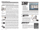
Figure 17: Linx Antennas
Antenna
Transmitter
Module
Receiver
Module
0.1
μF
0.1
μF
0.1
μF
0.1
μF
0.1
μF
GND
V
DD
Select
GND
Figure 18: Typical Antenna Switch
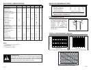
GENERAL ANTENNA RULES
The following general rules should help in maximizing antenna performance.
1. Proximity to objects such as a user’s hand, body, or metal objects will cause an
antenna to detune. For this reason, the antenna shaft and tip should be
positioned as far away from such objects as possible.
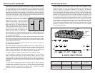
2. Optimum performance will be obtained
from a 1/4- or 1/2-wave straight whip
mounted at a right angle to the ground
plane. In many cases, this isn’t desirable
for practical or ergonomic reasons, thus,
an alternative antenna style such as a
helical, loop, or patch may be utilized
and the corresponding sacrifice in performance accepted.
3. If an internal antenna is to be used, keep it away from other metal components,
particularly large items like transformers, batteries, PCB tracks, and ground
planes. In many cases, the space around the antenna is as important as the
antenna itself. Objects in close proximity to the antenna can cause direct
detuning, while those farther away will alter the antenna’s symmetry.
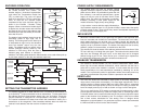
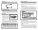
4. In many antenna designs, particularly 1/4-wave
whips, the ground plane acts as a counterpoise,
forming, in essence, a 1/2-wave dipole. For this
reason, adequate ground plane area is essential.
The ground plane can be a metal case or ground-fill
areas on a circuit board. Ideally, it should have a
surface area >
the overall length of the 1/4-wave
radiating element. This is often not practical due to
size and configuration constraints. In these
instances, a designer must make the best use of the
area available to create as much ground plane as
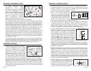
possible in proximity to the base of the antenna. In cases where the antenna is
remotely located or the antenna is not in close proximity to a circuit board,
ground plane, or grounded metal case, a metal plate may be used to maximize
the antenna’s performance.
5. Remove the antenna as far as possible from potential interference sources. Any
frequency of sufficient amplitude to enter the receiver’s front end will reduce
system range and can even prevent reception entirely. Switching power
supplies, oscillators, or even relays can also be significant sources of potential
interference. The single best weapon against such problems is attention to
placement and layout. Filter the module’s power supply with a high-frequency
bypass capacitor. Place adequate ground plane under potential sources of noise
to shunt noise to ground and prevent it from coupling to the RF stage. Shield
noisy board areas whenever practical.
6. In some applications, it is advantageous to
place the module and antenna away from the
main equipment. This can avoid interference
problems and allows the antenna to be
oriented for optimum performance. Always use
50Ω coax, like RG-174, for the remote feed.
NUT
GROUND PLANE
(MAY BE NEEDED)
CASE
Figure 21: Remote Ground Plane
OPTIMUM
USEABLE
NOT RECOMMENDED
Figure 19: Ground Plane Orientation
I
E
DIPOLE
ELEMENT
GROUND
PLANE
VIRTUAL λ/4
DIPOLE
λ/4
λ/4
VERTICAL λ/4 GROUNDED
ANTENNA (MARCONI)
Figure 20: Dipole Antenna