


INSTALLATION
STEP 1. Remove antenna from carton and
unfold elements until they lock into place.
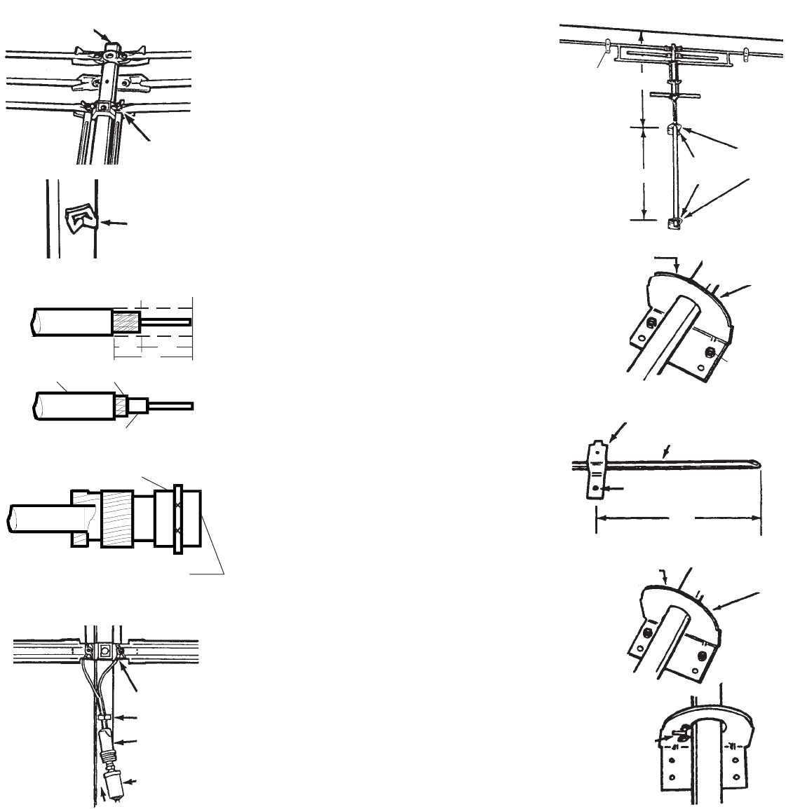
STEP 2. Connect loose elements to stud
rivets. Use flat washers and wing nuts from
hardware bag to secure loose elements. See
Figure 1.
STEP 3. Insert boom plugs into top and
bottom of mast. See Figure 1.
STEP 4. Insert retaining clip into hole just
below downlead connection. See Figure 2.
STEP 5. Slide weather boot from matching
transformer onto coax. To install the F-con-
nectors, strip the ends of the RG-59 cable as
shown in Figure 3A.
STEP 6. Push back and twist the braid around
the Dielectric until it butts against the cable
jacket. See Figure 3B.
STEP 7. Screw the F-connector onto the
cable jacket until the Dielectric butts against
the inner retaining ring. Cut the center con-
ductor off flush with the end of the connector.
See Figure 3C.
STEP 8. Attach matching transformer to
downlead stud rivets with washers and wing
nuts supplied from hardware bag. See Figure
4.
STEP 9. Screw coax downlead onto match-
ing transformer, making sure to slide weather
boot over connection. See Figure 4.
STEP 10. Secure matching transformer to
retaining clip. See Figure 4.
STEP 11. Select location on vehicle for an-
tenna where downlead entry will be made and
where antenna may be lowered without pro-
truding above roof line. Hold antenna in posi-
tion and mark location of mast to aid in mount-
ing mast brackets.
STEP 12. Mount mast bracket 22" below
roof line. Use two (2) #10 x 1" sheet metal
screws provided in hardware bag. See Fig-
ure 5. Mount bottom bracket 18" below top
mast bracket, making sure brackets line up
vertically. See Figure 5.
STEP 13. Slide antenna assembly down
thru mast brackets. Insert locking bolt thru
top hole in mast so it will be above lower
mast bracket. See Figure 6. Antenna should
rest on locking bolt.
STEP 14. Place storage brackets approxi-
mately 12" from end of long VHF element
and attach to vehicle with one (1) #10 x 1"
sheet metal screw. See Figure 7.
STEP 15. Run downlead to TV set, leave
enough slack so antenna may be raised.
To Raise Antenna to Operating
Position:
Remove locking bolt and wing nut from hole
in center of mast, slide antenna up thru
brackets until hole at bottom of mast is just
above bottom mast bracket and insert lock-
ing bolt and secure with wing nut. See
Figure 5.
NOTE: Antenna may be rotated when in
the operating position to obtain best
picture.
To Lower Antenna to Travel Position:
Rotate antenna until elements are on side
facing vehicle. Remove locking bolt and
wing nut, slide antenna down thru mast
brackets until VHF element rests on stor-
age brackets. Replace locking bolt in top
hole below bottom mast bracket and secure
bolt and wing nut. See Figure 9.
RG/59
RG/59
Dialectric
Center
Conductor
Jacket Twist Braid over Jacket
1/4"
1/2"
3/4"
Figure 3B
RG/59
Type F-Connector
Center Conductor to
be Flush With End of
Connector.Figure 3C
Figure 4
WING NUT
& WASHER
MATCHING
TRANSFORMER
WEATHER
BOOT
LOCKING
BOLT &
WING NUT
Figure 9
Figure 8
LOWER BRACKET
LOCKING BOLT
THROUGH
LOWER HOLE
STORAGE BRACKET
VHF ELEMENT
#10 x 1" SCREW
LOWER MAST
BRACKET
LOCKING
BOLT THRU
TOP HOLE
MAST
BRACKETS
Figure 6
12"12"
12"12"
12"
Figure 2
Figure 1
Figure 3A
ROOF LINEROOF LINE
ROOF LINEROOF LINE
ROOF LINE
22"22"
22"22"
22"
RETAINING
CLIP
BOOM PLUG
#10 x 1"
SCREWS
Figure 7
Figure 5
WING NUT &
FLAT WASHER
CLIP
STORAGESTORAGE
STORAGESTORAGE
STORAGE
BRACKETSBRACKETS
BRACKETSBRACKETS
BRACKETS
BOTH SIDESBOTH SIDES
BOTH SIDESBOTH SIDES
BOTH SIDES
STEP 14STEP 14
STEP 14STEP 14
STEP 14
#10 x 1"
SCREWS