


5
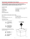
IMPORTANT! Do not install this system
in the rain, or under any wet conditions. Mois-
ture may affect electronics and void your
warranty!
1. For best performance and to reduce signal ac-
quisition time, park vehicle on a level surface;
level the RV.
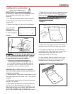
2. Select a level spot on your roof for installation.
Using the chart,
determine the
minimum distances
to other equipment.
WARNING: Level the base front to back and side
to side. If base is not level the MV3500T may re-
quire more time to locate the correct satellite
or may not locate the correct satellite.
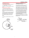
• Be sure no roof-mounted equipment is
blocking the satellite “line of sight”, Fig. 3
• You will need to decide where the wires will enter
the vehicle. A coax and a power wire (minimum 16
gauge) will need to be run into the vehicle.
WARNING: Many +12VDC sources can cause the
unit to fail. Select a filtered source, preferably a dedi-
cated line to the battery.
!
Installation
Install in DRY conditions only!
Installing unit on roof of vehicle —
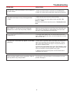
Obstruction Ht. Unit Clearance
8” .......................................... 4”
10” ................................... 11.5”
12” ...................................... 19”
15” ...................................... 32”
FIGURE 3
OBSTRUCTION
UNIT BASE
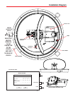
3. Remove dome. Place dome in safe spot to avoid
damage. Place base on vehicle roof in the location
selected.
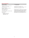
4. Attach each mounting foot to base by securing
with two 7/16” nylocks.
5. After selecting location for unit (see number 2),
put the unit on the centerline of the vehicle.
REAR MOUNTING FOOT MUST BE PARALLEL
WITH THE CENTER LINE OF VEHICLE. See pg. 4.
FIGURE 4
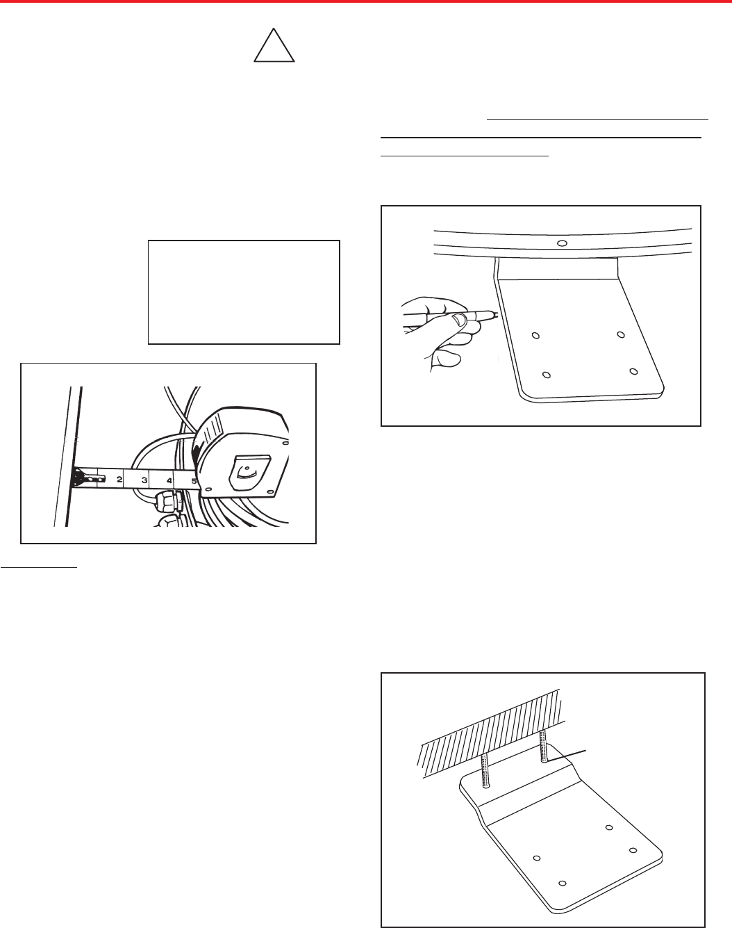
8. Clean roof area where the base feet will be
attached to the roof. Do not erase your marks!
9. Put approved sealant in the areas marked
for the base feet. Place base feet on top of the
sealant and screw down with the (4) #10
screws (provided) for each foot.
10. After all base feet are secured to roof, put
sealant around edge of feet and over screws.
Replace base on screws and reinstall nut.
FIGURE 5
BASE EXTERIOR
FOOT
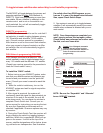
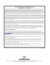
7. Place the unit on the roof in its permanent loca-
tion and mark around each base foot, Figure 4.
(Make sure the
rear base foot is PARALLEL to
the center line of the coach and FACING to-
wards BACK of vehicle!) See pg. 2.