


4
Quick Reference Guide
Your Winegard RoadTrip satellite System has been designed to be the most user-friendly
Mobile Satellite Antenna on the market today. Upon installation of the antenna, or after
changing satellite service provider, simply set the switches inside of the dome to the settings
shown in the Operation manual. These switches enable the dish to locate the proper satellite
for your service provider, and, for the RoadTrip SDi In-Motion system, to be set for the proper
installation option. Simply set the switch, and forget it! Your Winegard RoadTrip Satellite
Antenna will locate the proper satellite with just the flip of a switch.
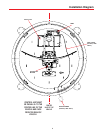
Mounting Instructions
It is essential to mount your RoadTrip Automatic System in the proper position and orientation
on your RV roof to ensure proper operation. Choose a location on your roof clear of
obstruction and close to your receiver and power source.
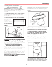
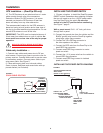
To ensure proper tracking with your RoadTrip SDi, you must mount the unit so that the unit is
centered on the centerline and cables exit either towards the front or back of the RV. See
Figure 1c below.
MOUNTING OPTION A
CABLE EXIT REAR
CENTER LINE OF VEHICLE
MV-3500
BACK OF VEHICLE
FRONT OF VEHICLE
ROADTRIP
CABLE EXIT FRONT
CENTER LINE OF VEHICLE
MV-3500
BACK OF VEHICLE
FRONT OF VEHICLE
FIGURE 1C
MOUNTING OPTION B
ROADTRIP
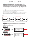
Switch Settings
After mounting the RoadTrip System to your rooftop, you must set the RoadTrip’s switch
settings for the mountoing options chosen and satellite Television Service Provider. The chart
below lists switch settings for both the RoadTrip SD and RoadTrip SDi. See page 3. of
Operation Manual for detailed instructions.
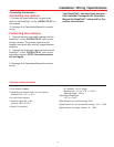
RoadTrip SD
(#1 represents Switch DOWN; #0 represents Switch up)
Sat. Rcvr. Mt. Option Switch Set Position
................................... 1 2 3 4 5 6 7 8
DIRECTV A 0 0 0 0 0 0 0 1
(FACTORY PRESET)
DISH NETWORK A 0 0 0 1 0 0 1 1
1 2 3 4 5 6 7 8
SWITCH SETTINGS
SHOWN
0= UP 1= DOWN
1 = DOWN
0 = UP
0 0 0 0 0 0 0 1
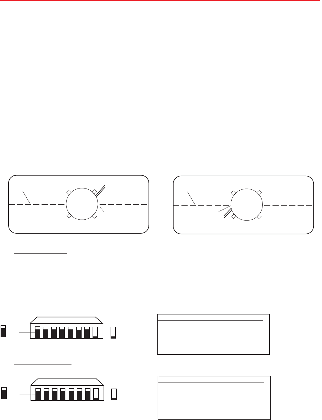
RoadTrip SDi
(#1 represents Switch DOWN; #0 represents Switch up)
Sat. Rcvr. Mt. Option Switch Set Position
..................................... 1 2 3 4 5 6 7 8
DIRECTV A 0 0 0 0 0 0 0 1
(FACTORY PRESET)
DIRECTV B 1 0 0 0 0 0 0 1
DISH NETWORK A 0 0 0 1 0 0 1 1
DISH NETWORK B 1 0 0 1 0 0 1 1
1 2 3 4 5 6 7 8
SWITCH SETTINGS
SHOWN
0= UP 1= DOWN
1 = DOWN
0 = UP
0 0 0 0 0 0 0 1
™
TM
TM
TM
TM
TM