


2
SPECIFICATIONS
Electrical Ratings [@ 77
o
F (25
o
C)]:
Rated Voltage ..................................... 24 VAC
Rated Voltage Range ............................... 18-30 VAC
Max. Power Consumption @ 24 VAC .................. 4.08 VA
Nominal Frequency................................. 50/60 Hz
Relay Load Ratings:
Compressor Contactor Relay ...................... 20 VA in rush, 6 VA holding
Fan Relay...................................... 1/2 HP @ 240, 1/4 HP @ 120 VAC
Reversing Valve Relay (RV) ........................ 24 VA
Auxiliary Heat Relay (D)........................... 1 Amp. 0.6 P.F.
Operating Temperature Range ........................ -40
o
to 150
o
F (-40
o
to 65
o
C)
Humidity Range ................................... 5% to 95% relative humidity
(non-condensing)
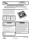
Timing Specications @ 60Hz*
Nom Units
Defrost Lockout Time 34 Mins.
Maximum Defrost Time 14 Mins.
Transient Delay 2 Mins.
Maximum Frosting Time 6 Hrs.
Short Cycle Lockout Time 5 Mins.
Noise Abatement Time 5 Sec.
*50Hz Timings are 20% longer.
The control is recognized by UL as an incorporated
electronics control per UL 60730-1A. This control does
not perform any safety/protective functions. This device is
automatic, type 1 action, incorporated control.
OPERATION
Each controller has 24 VAC input and B, Y, and D terminals
for connection to a standard thermostat. The controller has
pins for connection of two temperature sensors to measure
ambient and coil temperature. Controlled outputs are outdoor
fan, reversing valve, and compressor contactor.
The controller has a LED to indicate system operation status.
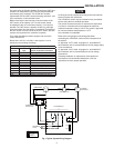
Option Switch
Switch labeled SW1 is used to select the defrost mode
termination temperature of outdoor coil. Defrost mode is
terminated when the coil temperature exceeds the selected
termination temperature. Temperature options for SW1 switch
settings are:
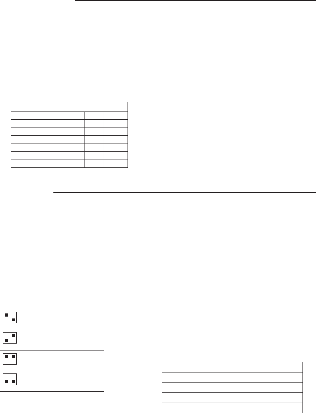
LED Fault Indication Display Priority
ON Normal 0
1 Flash Defrost mode 1
2 Flashes Coil sensor fault 3
3 Flashes Ambient sensor fault 2
Short Cycle Protection
The control includes protection against short cycling the
compressor. At power-up, and each time the Y input is
interrupted, the control will enter a 5-minute short cycle
lockout period. During this lockout, the control will not
energize the compressor contactor, even if a call for heating
or cooling is received on the Y input. The control will resume
normal operation when the lockout period expires.
Noise Abatement
When the reversing valve is switched during an active call for
heating or cooling, such as when entering or leaving a defrost
cycle, the control will de-energize the compressor contactor
for 5 seconds in order to reduce compressor noise.
Diagnostic Features
The control continuously monitors system operation. If a fault
occurs, the red LED on the control will flash a diagnostic
code, if more than one fault occurs, only the code with the
higher priority will flash. The flash time is to be 0.5 seconds
on and 0.5 seconds off followed by 2 seconds off. The table
shows the diagnostic codes:
B A
On Off 50
o
F
Off On 60
o
F
On On 70
o
F
(default)
Off Off 80
o
F
B A
B A
B A
B A
Test Pins
The connector labeled TEST can be used to change
operation mode in the field. Momentarily short the test pins
to force the system into the defrost mode. Momentarily short
the test pins again to terminate the defrost mode. To avoid
unnecessary system mode transition, do not use the test pins
frequently.