


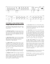
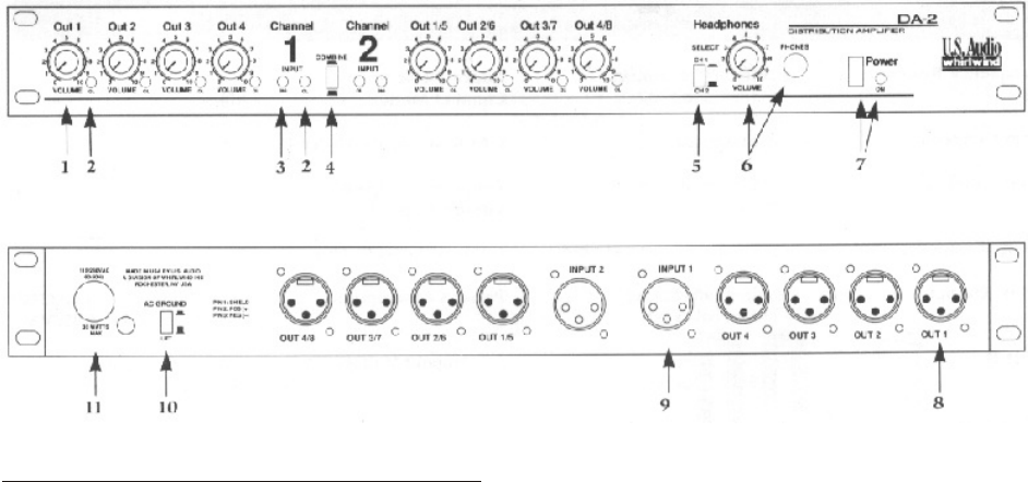
1. Output Volume Pots control the level at the
corresponding rear panel output XLR. Each of the controls
has a gain range of -60dB attenuation at full off to + 18dB
of gain at full on.
2. Individual Clip LEDs on all 8 outputs and on each of
the two inputs indicate signal overload conditions within
the circuitry. The red clip lights illuminate at 3dB below
actual clipping (the unit clips at ±28dB balanced, the LEDs
illuminate at +25dB).
3. Signal Present LEDs on each of the input channels
indicate that signal is being applied to the input. The green
lights illuminate when the input signal is greater than
-14dB balanced or -20dB unbalanced.
4. Combine Switch converts the DA-2 from a 2 by 4
configuration to a 1 by 8 distribution amp. In this mode the
two inputs are actively mono-summed or either input may
be used to feed the eight outputs. The mono-sum feature
allows the DA-2 to properly combine left and right stereo
signals into a mono feed.
5. Channel 1/2 Select Switch determines which channels
input signal is fed to the headphone circuit for monitoring.
6. Headphone Circuit monitors the signals coming into
the DA-2 inputs. It is a mono circuit which drives both
earpieces in stereo headphones that have an impedance
greater than 20 Ohms. The volume control has a gain range
of -60 to +18dB to accommodate a wide range of audio
levels. The jack is a standard 1/4” TRS type.
7. Power Switch connects AC to the transformer primary
and the LED indicates that the unit is working. Both sides
of the AC line are switched and a mains fuse is located on
the circuit board inside the unit.
8. Output XLR5 on the DA-2 are actively balanced with
the audio ground lifted (pin 1 disconnected). If grounding
pin 1 of the XLR is required, there is a spot for a jumper for
each XLR output on the PC board. Each output is driven
with its own individual driver circuit providing channel-to-
channel isolation greater than 74dB. The outputs are wired
pin-2 positive, pin-3 negative and are RF-bypassed with
capacitors for rejection of RF signals on the output lines.
9. Input XLR Connectors feed actively balanced
differential amplifiers providing over 90dB of common
mode rejection. The input impedance is factory-set at 1Meg
Ohms, allowing the inputs of many units to be paralleled
together. If lower input impedance is desired it can be
easily accomplished by an internal resistor change. In
Combine mode inputs 1 and 2 are actively summed to
mono. Pin-2 is positive, pin-3 negative and pin-1 is
connected to audio ground.
10. Ground Lift Switch connects the audio circuit ground
to AC ground and the chassis of the unit, if desired.
11. Power Cord - a standard 15 amp plug for l20VAC and
has no plug on the DA-2X 230VAC model. Black is line,
white is neutral and green is earth.
CONTROLS AND CONNECTIONS