


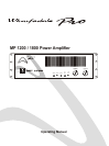
POWER AMPLIFIER
4
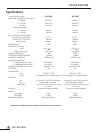
MP 1200/1800
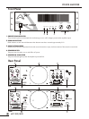
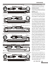
1. FANS
The fans should be kept free of all obstructions and be accessible to cool fresh air when possible. It is important that the
fans be used in a dust free environment.
4. AC INLET
Plug this AC input cord into AC outlet.
2.OUTPUTS
Loudspeaker outputs are on large diamete 30A binding posts or Speakon NL4 connectors. The binding posts may be used in 3
ways. In order of preference:-
a) Use a quality 4mm Banana plug, colour coded, into the back of the binding posts.
b) Bare wire through the hole in the post, screwed down tight. This provides a very good electrical contact which is also very
secure. Use the heaviest gauge speaker cable possible. A 4mm banana plug may be similarly clamped in this way.
c) Bare wire may be wrapped around the post and the clamp screwed down. Be sure to wind the wire CLOCKWISE so that
screwing down the clamp tightens the wrap. This gives a good electrical connection and is secure if done Properly.
The SPEAKON sockets are wired: - l+ = positive, 1- = negative. 2+ and2- are not used under normal operations.
3.INPUTS
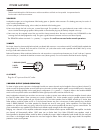
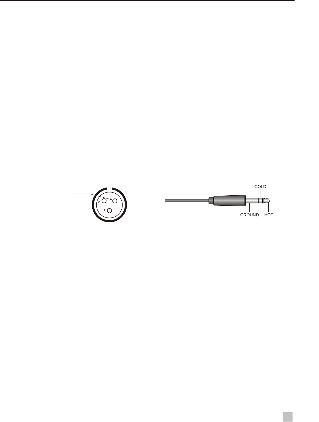
Each input channel is electronically balanced with one female XLR connector. in accordance with IEC and AES/ANSI standards the
wiring mode is Pin 1 Ground, Pin 2 Hot and Pin 3 Cold. the 1/4" Jack socket is also wired in parallel with the XLR'S. the Tip is Hot,
the ring is Cold and the sleeve is Ground.
Balanced Operation: Either transformer balanced or with active drive. connect the input between pins 2 and 3 with pin 2 positive.
do not connect pin 1, attached the shield to connector case (classes ground). Do not connect the shield at this end to anything.
5 BRIDGED OUTPUT (MONO OPERATION)
To obtain a higher power output into a loudspeaker load the two stereo channels may be bridged to form one (Mono) channel. To
do this connect the positive speaker wire to the RED post on channel-A, and the negative speaker wire to the RED post on channel-B.
Alternatively the bridge Speakon can be used (the pin configuration is l + = positive, 1- = negative). When in this mode the BRIDGE
switch on the rear panel should be set to BRIDGE and the signal input should be wired to channel A only.
Many loudspeaker cabinest have more than one connector in order to connect extra cabinets to the same amplifier channel without
the need for splitter cables. These connectors are wired in PARALLEL. Two 16ohm speakers wired in parallel equates to 8ohm
(16/2=8). Three 16ohm speakers will give 5.3ohm(16/3=5.3). Two 8ohm speakers wired in SERIES will add up to 16ohm, three
8ohm speakers would be 24ohm and so on. To share power between two pairs or three pairs of similar speakers, they should be
wired in SERIES/PARALLEL. Two 8ohm speakers for example are wired in series giving 16ohm impedance. Two further 8ohm
speakers are wired in the same way, giving 16ohm. Each pair is then wired in paralled with the other to give a nominal 8ohm. The
power available from any amplifier into an 8ohm load is shared equally amongst the four 8ohm speakers.
Bridging two channels of an amplifier combines the outputs to obtain twice the power. A600+600 watt amplifier into 4ohm
per channel will theoretically deliver 1200 watts into an 8ohm load. Four 8ohm 300-400 watt speakers wired in
series/parallel as described above would be able to handle this output. 4ohm loudspeaker loads should only be used with
care when in the bridged mode because the true load might be below 2ohms and at high output levels the amplifier's
protection circuits could operate.
1. GROUND (shield)
2. HOT+
3. COLD-
1
2
3