


4
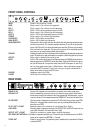
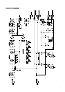
FRONT PANEL CONTROLS
INPUT Socket for the connection of a bass
BASS Rotary control to Cut or Boost low frequencies
MID 1 Rotary control to Cut or Boost low-mid frequencies
SHIFT 1 Switch + LED to set the operating frequency of MID 1
MID 2 Rotary control to Cut or Boost high-mid frequencies
SHIFT 2 Switch + LED to set the operating frequency of MID 2
TREBLE Rotary control to Cut or Boost high frequencies
LOW BOOST Switch + LED to Boost low frequencies
HIGH BOOST Switch + LED to Boost high frequencies
QUADRUMATRIX Rotary switch to alter the basic character of the Quadruplet. Also alters the operating frequen-
cies of the tone controls. (For frequency diagrams see below) Q1 and Q2 are pure preamp
signals. With Q3 and Q4, the valve(tube)-based power amplifier (EL84 and output transfor-
mer) is included in the signal path. This gives you the sounds of a full-valve(tube) amplifier,
even when you are using a transistorbased power amplifier.
CRUNCH Amplifies the signal at the input to the preamp whilst simultaneously attenuating the signal at the
output. This allows you to apply valve overdrive to compress or distort the signal from your bass
OUTPUT Rotary control to determine the overall volume.
MUTE Switch + LED mutes all the outputs of the Quadruplet except the PHONES socket and simul-
taneously activa tes the TUNER OUT socket (Rear Panel). When the MUTE switch is depres-
sed, the LED shines red. In an operation ready state, the LED shines green. In case of sig
nal flow at the power section (Input or Effects Return), there might appear a popping
noise when MUTE is pressed. To avoid this, mute your strings or have effects like
delays muted when pressing the MUTE button.
PHONES Headphone socket (min 200Ω).
POWER On/Off switch for the Mains Power.
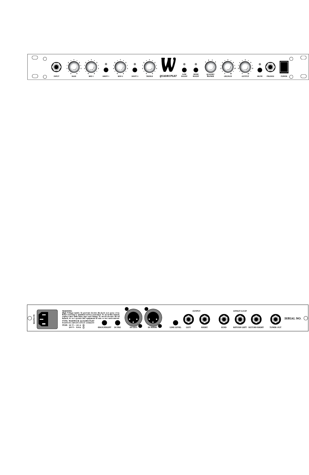
REAR PANEL
MAINS IN AC Terminal with integrated fuse compartment for connection to the mains power supply
GROUND LIFT Switch to separate the grounding conductor from the audio signal ground. When several
devices are grounded to the same point and interconnected with shielded cables, a ground
loop hum can result. If this happens, depress the GROUND LIFT switch to eliminate the hum.
DI PRE/POST When this switch is depressed, the signal at the DI OUT socket is the pure bass signal (PRE).
Otherwise it is the signal after the tone controls and any connected effects devices have
done their work (POST)
DI OUT LEFT + RIGHT Balanced outputs for the connection to a mixing desk (PA or Studio).
LINE LEVEL When this switch is depressed, the output of the OUTPUT LEFT and RIGHT sockets is at Line
Level (0dB). Otherwise it is at Instrument Level (+6dB)
OUTPUT LEFT + RIGHT Outputs for connection to a power stage or amplifier (see above)
EFF. SEND & EFF. RETURN L + R Sockets to implement the effects loop. Connect the input of the effects device to the SEND
socket and its outputs to the RETURN L + R sockets
TUNER OUT Socket for a tuning device. The pure bass signal is available at this socket when the Preamp
is switched MUTE