


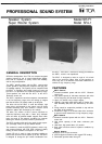
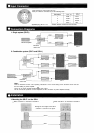
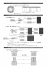
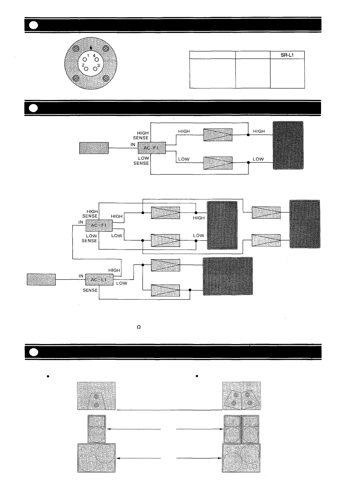
Input Connector
Connection Diagrams
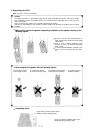
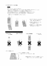
Installation
Input connector is used Cannon EP-4-14.
Each pin number is connected as per the following table.
Pin number
1
2
3
4
SR-F1
LOW +
LOW
-
HIGH -
HIGH +
*LEFT -
RIGHT -
RIGHT +
LEFT +
Applicable plug: EP-4-11-1C
* Woofer direction viewed from the front side.
1. Single system (SR-F1)
2. Combination system (SR-F1 and SR-L1)
Mixer/Preamplifier
Electronic
control unit
Power amplifier
SR-F1
Power amplifier
SR-F
1
SR-L1
Electronic
control unit
Mixer/Preamplifier
Note:
Refer to "Electronic control unit's operating instructions" on the mode setting of the electronic control unit and
the level setting of power amplifier.
Secure to use power amplifier 300W (8 ) or more output.
Do not connect two speakers or more in parallel, or BTL connection of power amplifier basically.
1. Mounting the SR-F1 on the SR-L1
When one SR-F1 is mounted on the SR-L1.
When two SR-F1 are mounted on the SR-L1.
Arrange the front edges of the SR-F1
and SR-L1 as shown in the figure.
SR-F1
SR-L1
SR-F1