


continued. . .
6
☞
☞
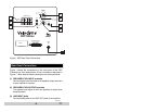
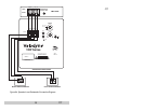
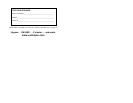
Figure 1. VRP Rear Panel Connections
Rear Panel Connections
Figure 1 shows the connections on the rear panel of the VRP.
Following are brief descriptions of the connections described in
Figure 1. More detail of these connections can be found below:
(1) SPEAKER LEVEL INPUT terminals
Connect these input terminals to the speaker output terminals
of your amplifier or receiver.
(2) SPEAKER LEVEL OUTPUT terminals
The speaker-level signal to the front speakers is output from
these terminals.
(3) LINE INPUT jacks
Connect these jacks to the LINE OUT jacks of the amplifier.
(AUDIO APPARATUS)
68BM E203436
C
US
US
R
I
S
T
E
L
D
LISTEDLISTED
2A
120V~
60Hz
+ R -
- L +
INPUT
OUTPUT
SPEAKER LEVEL
+ R -
- L +
LOW-PASS
CROSSOVER
200Hz
80 Hz
50Hz
PHASE
0
0
180
0
SUBWOOFER
VOLUME
MIN MAX
VRP Series
INPUT
R
L
LFE IN
RED : STANDBY
GREEN : ON
VELODYNE ACOUSTICS, INC.
MORGAN HILL, CA.
SERIAL #
3
2
1
4
5
6
7
RISK OF ELECTRIC SHOCK
DO NOT OPEN
CAUTION
WARNING: TO REDUCE THE RISK OF FIRE
OR ELECTRIC SHOCK. DO NOT EXPOSE
THIS APPLIANCE TO RAIN OR MOISTURE.
AVIS:
RISQUE DE CHOC ELECTRIQUE-NE PAS OUVRIR
DOUBLE INSULATION - WHEN SERVICING USE ONLY IDENTICAL REPLACEMENT PARTS
100Watt
4 ~ 8 Ohm