


4
.
www.velodyne.com
VDR Series User’s Manual
F
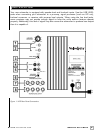
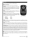
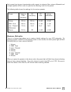
igure 1 shows the connections on the rear panel of the VDR.
Following are brief descriptions of the connections described in Figure 1. More detail on these
connections can be found on the next page.
(1) LOW-PASS CROSSOVER
Use this knob to select the high-frequency range at which you wish to cut off the signal to
the subwoofer. When the knob is turned all the way to the left (counter-clockwise), the
Subwoofer Direct feature is invoked and the subwoofer plays all frequencies up to 200 Hz.
(2) VOLUME Control
This control allows you to balance the output from the subwoofer to the main speakers in
your system. This control should be set to achieve similar volume level from between both
the main speakers and subwoofer. When pressing volume up or down, the speed at which
the power light blinks indicates subwoofer volume - the faster the blinking, the louder the unit
plays. After the volume blinking stops, the unit will blink out the actual volume number. Slower
blinks represent tens, and faster blinks represent ones. So, for example, if the volume were
set at 34, after the rapid blinking stopped you would observe three slow blinks followed by
four faster blinks, indicating a volume of 34.
Note: Volume is also controllable by using the supplied remote, when defaults are restored.
The default is 30 out of 100.
(3) AUTO ON/OFF Switch
Use this switch to select between auto-on (active) and constant on (inactive) operation.
(4) LINE OUTPUT
Connect these jacks to the LINE IN of the power amp or r
eceiver input to use the VDR
internal high pass crossover. See below for a more detailed explanation of this crossover.
(5) LINE INPUT/LFE Input
Connect these jacks to the LINE OUT preamp output, LFE output, or subwoofer output jacks
of your r
eceiver/pr
ocessor. If using the LFE output from your receiver or processor, plug the
single cable into the “L” – LFE input or, for more signal, use a “Y” connector (not included)
and feed the signal into both “R” and “L” inputs.
(6) HIGH PASS CROSSOVER Switch
This switch selects the frequency for the high pass crossover. This crossover is functional
on both line and speaker
-level outputs. Smaller speakers with limited low fr
equency output
may perform better using the higher 100 Hz setting that will reduce the low frequencies sent
to them. Lar
ger speakers with gr
eater low frequency output may be able to handle the 80
Hz setting without strain.
(7) SPEAKER LEVEL INPUT Terminals
Connect these input terminals to the speaker output terminals of your amplifier or receiver.
If you use this method of connection, when you go to the receiver speaker set up menu, make
sure you select the large speaker option
Rear Panel Connections